TAM 00695
12
DST2-135
– 400 W
10 / 2019
Three-phase synchronous motor, water-cooled
English
When using standard solvents such as Acetone or benzine, the shaft sealing ring must not be
moistened!
•
the motor is designed for the ambient conditions and environmental influences on site (see
Section 2.4
).
•
the compartment in the machine is suitable for the cooling method employed by the electric
motor (see
Section 2.6
).
The motor must be installed in such a way that the coolant lines can subsequently be
connected
.
•
there is enough room in the machine for connecting the motor and for inspection and
maintenance work.
For the installation dimensions of the motor and tolerance specifications, please refer to the
technical documentation or your provided dimensional drawing.
•
the motor can be mounted and operated with the connection data and fixing possibilities
provided.
The mounting dimensions of the motor and the tolerance details are provided in the technical
documentation.
When mounting the flanges on the motor, make sure that the flange surface rests well and
evenly. The supports and bearing surface must be clean and undamaged. They must be
precisely aligned with the connecting shafts to prevent the bearing, shafts and housing being
exposed to damaging loads through misalignment. When tightening the flange fixing screws,
(
min. property class 8.8
) make sure that the flange connection is not twisted
.
•
no liquid can penetrate the upper bearing when installing vertically with the shaft end facing
upwards.
Note:
Thrust-bearing motors may only be operated horizontally.
•
the permitted radial forces in accordance with the operating characteristics in the technical
documentation are not exceeded. If necessary, contact Baumüller. The motor manufacturer
must always be contacted in the case of axial forces.
•
the brake (optional) can be released after feeding the operating voltage (audible creaking
sound).
•
the rotor rotates smoothly without making a scraping sound.
If the motor is equipped with a brake, the brake should be released previously.
•
the design of the motor and encoder cables complies with the details in the technical
documentation.
•
the output and input elements are secured. With thrust-bearing and hollow-shaft motors,
sufficient contact protection on the open B-side shaft end during operation must be ensured.
•
the complete cooling circuit is leak proof and fully functional and protected against any foreign
objects falling into it.
•
3.3 Vibrations and resistance to vibrations
The vibration response of the entire system at the place of use, caused by output elements, mounting
conditions, alignment and installation as well as by influences of external vibrations, can lead to an
increase in the vibration values at the motor. Under certain circumstances a complete c balancing of
the rotor with the output element becomes necessary.
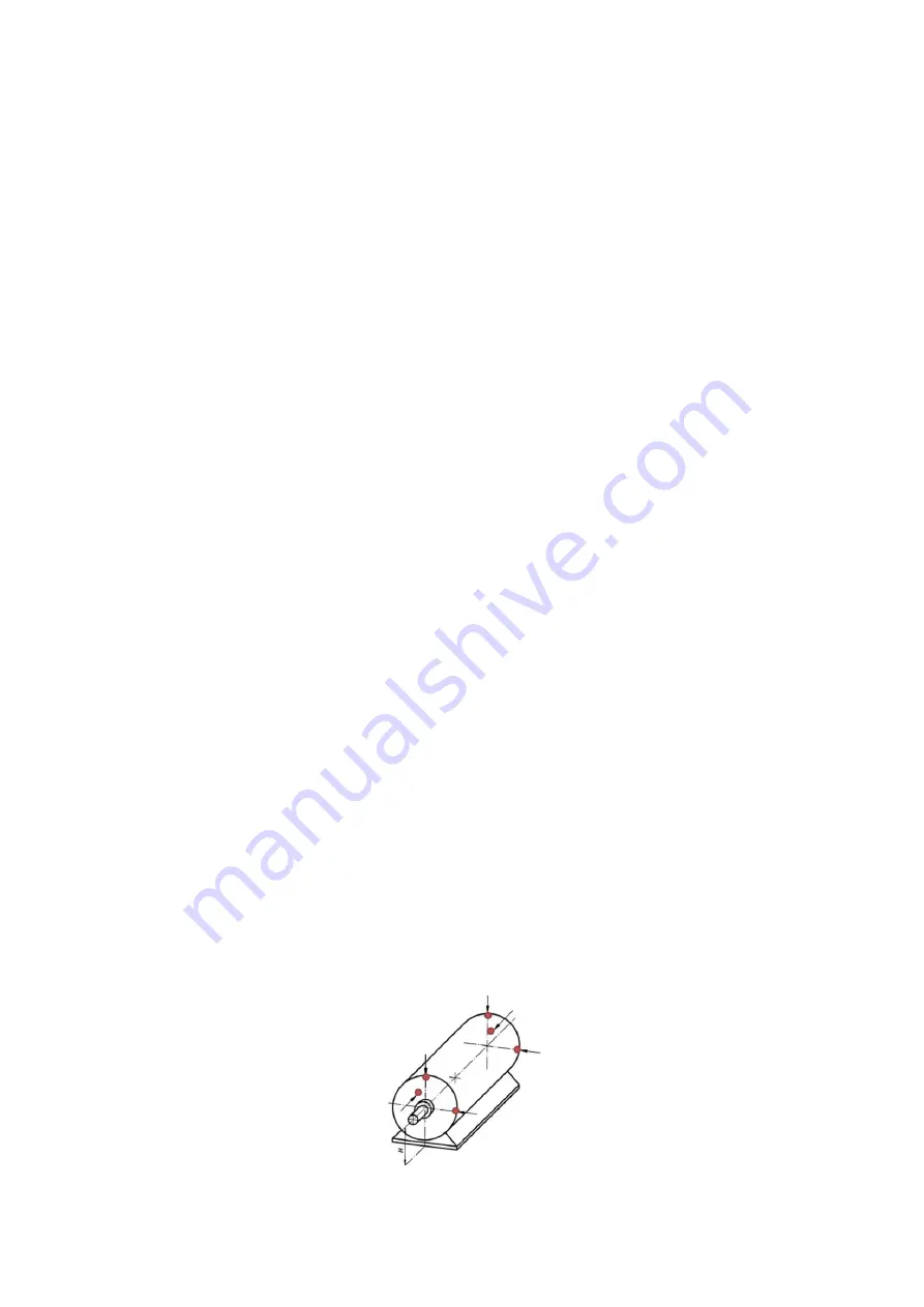
In order to be able to guarantee perfect function and service life the specified vibration values based
on DIN ISO 10816 must not be exceeded at the specified measuring points of the motor
(refer to figure 1).
Figure 1: Measuring points for vibration measurement


