Wiring diagrams
Instruction handbook
b maXX
BM5500, BM5600, BM5700
Document No.: 5.13008.10
Baumüller Nürnberg GmbH
192
7.11
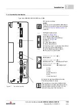
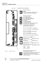
7.11.4 Requirements for the screwing
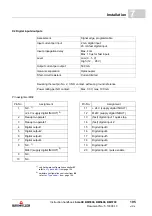
X100
(SELV/PELV)
Max. cross-section
of connection
Connection
technology
Load capacity
24 V power supply
1.5 mm
2
Terminal block
X100-1, X100-2, X100-5 and X100-
6: max.
8.0
A,
if you consider UL508C: max.
4.0
A
NOTICE!
It is forbidden to connect
both
the signal bus X300
and
the power supply bus/brake
resistor bus X100:3/X100:4. This leads to damage of the devices!
Refer to
Connection of several devices to the DC link without using the signal bus
X101
(SELV/PELV)
Max. cross-section
of connection
Connection
technology
Load capacity
Brake
BM551X
BM552X
1.5 mm
2
Terminal block
X101-1 bis X101-4:
Min.
0.1
A, max.
0.5
A
BM5532
BM5533
1.5 mm
2
Terminal block
X101-1 bis X101-4:
Min.
0.1
A, max.
1.0
A
BM5632
BM5534
BM5535
BM5X4X
BM5X5X
BM5X6X
BM5X7X
BM57XX
1.5 mm
2
Terminal block
X101-1 bis X101-4:
Min.
0.1
A, max.
8.0
A
if you consider UL508C:
max.
4.0
A
NOTE!
A relay with varistor protection circuit is required in case the customer connects an
additional relay.
NOTE!
Follow the mentioned torques to ensure an adequate conductivity.


