Additional data referring to water-cooled brake resistors
Instruction handbook
b maXX
BM5500, BM5600, BM5700
Document No.: 5.13008.10
Baumüller Nürnberg GmbH
114
3.6
Preconditions for the cooling versions F/W (through hole devices):
Provide adequate protection against contact. Install grids around the heat sink and the
resistors. Assure, that enough air can circulate and that no heat accumulation can devel-
op under the protective cover.
Preconditions for cooling version Z (mounting into the control cabinet):
Install the devices into the control cabinet, that no heat accumulation can develop above
the devices. Air circulation must be possible. In spite of air circulation elevated tempera-
tures can occur above the devices. Do not install cables or cable channels above the de-
vices. At the devices BM553X and BM554X do not install the connection cables directly
above the mounting plate of the device, where the hot air rises.
When dimensioning, consider that 10 % of brake resistor power is not dissipated via the
cooling water, but is an additional power loss, which heats the cabinet. Provide an ade-
quate fresh air supply.
Calculations
Precondition for calculation:
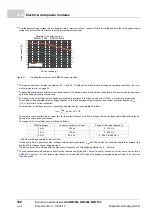
The brake power of the internal brake resistors must decrease straight proportional from
the brake peak power to 0.
The brake power time area A must be converted in an equivalent triangular time area. The
resulting parameters P
S
and t
on
must be used for the further calculations.
Figure 53:
Conversion brake power time area in triangular time area
on
on
A
t
1
P
S
1
2
---
t
2
P
S
+
1
2
---
t
on
P
S
=
=


