


51
8.4 Process Interface
8.4.1 Digital-IOs
8.4.1.1 User Definable Inputs
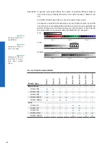
The wiring of these input connectors is the responsibility of the user.
The sole exception to this is the compliance with predetermined high and low levels
(only the optical input IN1; 0.0 ... 0.8V low, 3.3 ... 30V high).
The defined signals will have no direct effect, but can be analyzed and processed on the
software side and used to control the camera.
On the software side, the signal is named "Trigger".
Input Line 0
Trigger
state high
state low
state selection
(inverter)
◄ Figure 30
Input Signal
Содержание VEXG
Страница 2: ...2 ...
Страница 39: ...39 8 1 2 3 Pixel Formats VEXU Camera Type Mono8 Mono12 Bayer RG8 Bayer RG12 Monochrome VEXU 24M Color VEXU 24C ...
Страница 67: ...67 ...


