Baumer Hübner
Installation
|
5
V1 | PMG10 & PMG10P EtherCAT
Operating Manual
17
g) Fasten the coupling onto the shaft of the drive at a torque of 1.3 ±10 % Nm.
Observe the remarks in the data sheet and the coupling assembly instructions.
5.3
Maximum permitted tolerances for mounting errors when using the
Baumer Hübner K 35 spring washer
NOTICE
Damage to the encoder ball bearings.
Hard impacts of the drive shaft imposed on coupling parts may damage the ball bearings.
a) Prevent any hard impacts of the drive shaft on coupling parts.
Instruction:
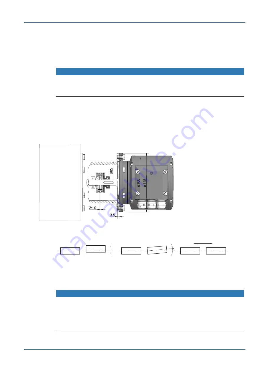
a) Mount the drive with small angular error and parallel offset.
b) Note the following allowable mounting errors:
The figure shows the device with EURO flange B10, the same maximum permissible mounting
errors must be observed for the device with housing foot B3.
±0.7 (±0.3*)
±0.2 (±0.05*)
±1°
* With insulated plastic hub
Permitted parallel misalignment
Permitted angle error
Permissible axial movement
Ill. 7:
Permissible mounting errors (dimensions in mm)
5.4
Notes when using a claw coupling (e.g. ROTEX®)
NOTICE
Damage to the rotary encoder due to incorrect mounting of the claw coupling.
Blocking of the two coupling halves (coupling claws lie face to face) can damage the rotary en-
coder.
a) Make sure that the coupling claws do not block.
b) Make sure that there is no direct axial stop on the device shaft.


