background image

23


Baumer_EEXGP02-TG74D_II_DE-EN  (18A1) 

MB053 - 11055655

12

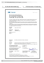
 EU-Konformitätserklärung

 / EU Declaration of Conformity

EU-Konformitätserklärung 


EU Declaration of Conformity 


Déclaration UE de Conformité 


Wir erklären in alleiniger Verantwortung, dass die Produkte, auf die sich diese Erklärung bezieht, die grund-

legenden Anforderungen der angegebenen Richtlinie(n) erfüllen und basierend auf den aufgeführten  

Norm(en) bewertet wurden. 
We declare under our sole responsibility that the products to which the present declaration relates comply 

with the essential requirements of the given directive(s) and have been evaluated on the basis of the listed 

standard(s). 
Nous déclarons sous notre seule responsabilité que les produits auxquels se réfère la présente déclaration 

sont conformes aux exigences essentielles de la directive/ des directives mentionnée(s) et ont été évalués 

sur la base de la norme/ des normes listée(s). 


Richtlinie(n) 

2014/30/EU; 2014/34/EU; 2011/65/EU; 2014/35/EU 

Directive(s) 

Klicken Sie hier, um Text einzugeben                                                                      


Directive(s) 

Klicken Sie hier, um Text einzugeben                                                                      


Norm(en) 

EN 60079-0:2012+A11:2013; EN 60079-1:2014; EN 60079-7:2015; EN ISO/IEC 80079-34:2011


Standard(s) 

EN 61000-6-2:2005; EN 61000-6-3:2007/A1:2011 ; EN 50581 :2012


Norme(s) 

EN 60034-1:2010+Cor.2010; EN 60034-5:2005/A1:2007; EN 60034-7:1993/A1:2001, EN 60664-1:2007    


Konformitätsbewertungsstelle:


TÜV NORD Cert  

Conformity assessment center 

Am TÜV 1 

Centre d‘évaluation et de mise en conformité 

30519 Hannover 


EU- Baumusterprüfbescheinigung:


TÜV 03 ATEX 2201 X 

EU type examination certificate 

Klicken Sie hier, um Text einzugeben                    


Attestation d'examen UE de type 

Klicken Sie hier, um Text einzugeben                    


Ort und Datum


Berlin, 12.06.2017 

Unterschrift/Name/Funktion 

Daniel Kleiner 

Place and date


Signature/name/function


Head of R&D Motion 

Lieu et date


Signature/nom/fonction


Control, Baumer Group 


Baumer_EExTacho_DE-EN-FR_CoC_81201528.docm/kwe  


1/1 


Baumer Hübner GmbH  P.O. Box 126943 ∙ D

-

10609 Berlin ∙ Max

-Dohrn-Str. 

2+4 ∙ D

-10589 Berlin 

Phone +49 (0)30 69003-

0 ∙ Fax +49 (0)30 69003

-

104 ∙ [email protected] ∙ www.baumer.com


Sitz der Gesellschaft / Registered Office: Berlin, Germany ∙ Geschäftsführer / Managing Director: Dr. Oliver Vietze, Dr. Joha

nn Pohany 

Handelsregister / Commercial Registry: AG Charlottenburg HRB 96409 ∙ USt

-Id-Nr. / VAT-No.: DE136569055 


EExGP 0.2 

TG 74 


Hersteller


Manufacturer 

Fabricant


Baumer Hübner GmbH 

Bezeichnung


Description 

Description


Tachogenerator 

Tachogenerators 

 Générateur tachymétrique  

Typ(en) / 

Type(s) /Type(s)


12


EU-Konformitätserklärung  

12


EU Declaration of Conformity  

Содержание EExGP 02-TG 74 d

Страница 1: ...ExGP 0 2 TG 74 d Tachogenerator mit Ex Schutzzulassung Tachogenerator with EX approval Montage und Betriebsanleitung Mounting and operating instructions MB053 11055655 Baumer_EEXGP02 TG74D_II_DE EN 18A1 ...

Страница 2: ...ritt 3 10 5 4 Schritt 4 10 5 5 Schritt 5 10 5 6 Schritt 6 11 5 7 Montagehinweis 12 5 8 Maximal zulässige Montagefehler unter Verwendung der Baumer Hübner Federscheibenkupplung K 35 13 6 Abmessung 14 7 Elektrischer Anschluss 14 7 1 Klemmenbelegung 14 8 Betrieb und Wartung 15 8 1 Austausch der Kohlebürsten 15 9 Demontage 16 9 1 Schritt 1 16 9 2 Schritt 2 16 9 3 Schritt 3 17 9 4 Schritt 4 17 9 5 Schr...

Страница 3: ... 4 10 5 5 Step 5 10 5 6 Step 6 11 5 7 Mounting instruction 12 5 8 Maximum permissible mounting tolerance when the Baumer Hübner K 35 spring disk coupling is used 13 6 Dimension 14 7 Electrical connection 14 7 1 Terminal assignment 14 8 Operation and maintenance 15 8 1 Replace of the carbon brushes 15 9 Dismounting 16 9 1 Step 1 16 9 2 Step 2 16 9 3 Step 3 17 9 4 Step 4 17 9 5 Step 5 17 10 Accessor...

Страница 4: ... Ein Wechsel der Kohlebürsten ist nur vorsorglich erforderlich 1 5 Der Lagertemperaturbereich des Gerätes liegt zwischen 15 C bis 70 C 1 6 Der maximale Umgebungstemperaturbereich für den Einsatz des Gerätes im Ex Bereich 2 G beträgt 20 C bis 55 C 1 7 EU Konformitätserklärung gemäß den europäischen Richtlinien 1 8 Wir gewähren 2 Jahre Gewährleistung im Rahmen der Bedingungen des Zentralverbandes de...

Страница 5: ... the carbon brushes is only a recommended precaution 1 5 The storage temperature range of the device is between 15 C and 70 C 1 6 In Ex areas 2 G the device must only be used within the ambient temperature range from 20 C to 55 C 1 7 EU Declaration of Conformity meeting to the European Directives 1 8 We grant a 2 year warranty in accordance with the regulations of the ZVEI Central Association of t...
Страница 6: ...gen technischen Dokumentation aufgeführte UL Listung gilt nicht für den Einsatz im Ex Bereich 2 4 Das Gerät darf nur in Betrieb genommen werden wenn die Angaben auf dem Typenschild des Gerätes mit dem zulässigen Ex Einsatzbereich vor Ort übereinstimmen Gerätegruppe Kategorie Zone Temperaturklasse bzw maximale Oberflächentemperatur die Angaben auf dem Typenschild des Gerätes mit dem Spannungsnetz ü...

Страница 7: ...from 20 C to 55 C 2 3 Any UL listing that may be quoted in any other technical documentation does not apply to use in the Ex area 2 4 Operation of the device is only permissible when the details on the type label of the device match the on site conditions for the permissible Ex area in use group of equipment equipment category zone temperature class or maxi mum surface temperature the details on t...

Страница 8: ...gen z B Hammerschläge können zur Zerstörung des Gerätes führen Niemals Gewalt anwenden Bei sachgemäßer Montage lässt sich alles leichtgängig zusammenfügen Für die Demontage geeignetes Abziehwerkzeug benutzen 3 4 Zerstörungsgefahr durch Verschmutzung Schmutz kann im Gerät zu dessen Beschädigung führen Während aller Arbeiten am Gerät auf absolute Sauberkeit achten Niemals Öl oder Fett in das Innere ...

Страница 9: ...lent shocks e g due to hammer impacts can lead to the destruction of the device Never use force Mounting is simple when correct procedure is followed Use suitable puller for dismounting 3 4 Risk of destruction due to contamination Dirt penetrating inside the device can damage the device Absolute cleanliness must be maintained when carrying out any work on the device Never allow lubricants to penet...

Страница 10: ... ø5 9 mm 8 Anschlussklemmen siehe Abschnitt 5 6 und 7 1 9 Erdungsanschluss 1 Housing 2 EURO flange B10 3 Solid shaft with key 4 Terminal box cover 5 Cylinder screw M4x30 mm ISO 4762 6 Spring washer 4 DIN 7980 7 Cable gland M16x1 5 mm for cable ø5 9 mm 8 Connecting terminal see section 5 6 and 7 1 9 Earth connection 4 Vorbereitung 4 1 Lieferumfang 4 Preparation 4 1 Scope of delivery 4 Vorbereitung ...

Страница 11: ...g K 35 als Zubehör erhältlich siehe Abschnitt 5 5 13 Anschlusskabel 10 Installation fitting customized 11 Fixing screw for installation fitting ISO 4017 M6x16 mm 12 Spring disk coupling K 35 available as accessory see section 5 5 13 Connecting cable 4 3 Erforderliches Werkzeug nicht im Lieferumfang enthalten 4 3 Required tools not included in scope of delivery 12x 2 5 und 3 mm 10 und 17 mm 14 Werk...

Страница 12: ... 2 Die Antriebswelle sollte einen möglichst kleinen Rundlauffehler aufweisen Rundlauffehler verursa chen Vibrationen die die Lebensdauer des Gerätes verkürzen können The drive shaft should have as less runout as possible Runouts can cause vibrations which can shorten the service life of the device 12 10 11 Siehe Seite 8 See page 8 Antriebswelle einfetten Lubricate drive shaft 2 5 mm 10 mm ...

Страница 13: ..._II_DE EN 18A1 10 Montage Mounting 5 5 4 Schritt 4 5 4 Step 4 5 3 Schritt 3 5 3 Step 3 5 5 Schritt 5 5 5 Step 5 Zul Anzugsmoment Max tightening torque Mt 2 3 Nm 12 2 11 5 6 4 7 Siehe Seite 7 oder 8 See page 7 or 8 2 5 mm 3 mm 17 mm 10 mm ...

Страница 14: ...ignete Kabel durchmesser zu verwenden To ensure the specified protection of the device the correct cable diameter must be used ø5 9 mm Siehe Seite 7 oder 8 See page 7 or 8 Zul Anzugsmoment Max tightening torque Mt 2 3 Nm Vor der Montage des Klemmenkasten deckels prüfen ob die Klemmenka stendeckeldichtung unbeschädigt ist Check that the seal of the terminal box is not damaged before mounting the te...

Страница 15: ...g 5 5 7 Montagehinweis 5 7 Mounting instruction i Wir empfehlen das Gerät so zu montieren dass der Kabelanschluss keinem direkten Wassereintritt ausgesetzt ist i It is recommended to mount the device with cable connection facing down ward and being not exposed to water ...

Страница 16: ...ading Zulässiger Parallelversatz Admissible parallel misalignment Zulässiger Winkelfehler Admissible angular error Zulässige Axialbewegung Admissible axial movement 0 2 0 05 1 Mit isolierender Kunststoffnabe With insulated hub 0 7 0 3 Die Montage an den Antrieb muss mit möglichst geringem Winkelfehler und Parallelversatz erfolgen Das harte Aufschlagen von Kupp lungsteilen auf die Welle ist wegen d...

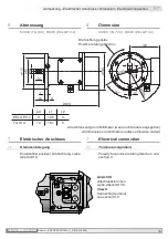
Страница 17: ...rität bei positiver Drehrichtung siehe Abschnitt 6 7 Electrical connection 7 1 Terminal assignment Polarity for positive rotating direction see section 6 Drehrichtung positiv Positive rotating direction Ansicht X Anschlussklemmen siehe Abschnitt 5 6 View X Connecting terminal see section 5 6 ød L1 L2 EEx GP 0 2 11 12 6 4 TG 74 d 14 16 1 5 A1 A2 Alle Abmessungen in Millimeter wenn nicht anders ange...

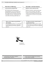
Страница 18: ...th L of 5 3 mm is reached the carbon brushes should be replaced and the com mutator area should be cleaned with dry compressed air in order to ensure perfect operation Kohlebürsten als Zubehör erhältlich Bestellnummer 11076778 Carbon brushes available as accessory Order number 11076778 Verlust der Ex Zulassung bei Öffnen des Gerätes Die Kohlebürsten dürfen nur vom Herstel ler ausgetauscht werden d...

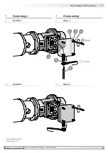
Страница 19: ...11055655 Baumer_EEXGP02 TG74D_II_DE EN 18A1 16 Demontage Dismounting 9 9 2 Schritt 2 9 2 Step 2 9 Demontage 9 1 Schritt 1 9 Dismounting 9 1 Step 1 5 6 4 7 8 13 Siehe Seite 7 oder 8 See page 7 or 8 3 mm 17 mm ...

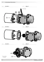
Страница 20: ...17 Baumer_EEXGP02 TG74D_II_DE EN 18A1 MB053 11055655 9 Demontage Dismounting 9 4 Schritt 4 9 4 Step 4 9 5 Schritt 5 9 5 Step 5 Siehe Seite 8 See page 8 9 3 Schritt 3 9 3 Step 3 12 11 10 mm 2 5 mm 2 5 mm ...

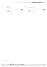
Страница 21: ...D_II_DE EN 18A1 18 Zubehör Accessories 10 10 Accessories Spring disk coupling K 35 Carbon brushes see table section 8 1 10 Zubehör Federscheibenkupplung K 35 Kohlebürsten siehe Tabelle Abschnitt 8 1 12 12 Siehe Abschnitt 3 See section 3 ...

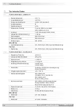
Страница 22: ...ach Bestellung TG 74 d Spannung 20 150 mV pro U min je nach Bestellung 11 2 Technische Daten mechanisch Baugröße Flansch ø90 mm Schutzart DIN EN 60529 IP54 T6 Drehmoment 1 5 Ncm Trägheitsmoment Rotor 1 15 kgcm2 Zulässige Wellenbelastung 60 N axial 80 N radial Werkstoffe Gehäuse Aluminium Gusslegierung Welle Edelstahl Umgebungstemperatur 20 55 C Widerstandsfähigkeit IEC 60068 2 6 Vibration 10 g 10 ...

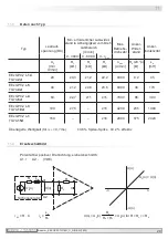
Страница 23: ... TG74 2d 20 0 3 1 2 2 2 8000 9 2 45 EExGP0 2 L 5 TG74 4d 40 1 2 4 8 8 6 8000 38 170 EExGP0 2 L 4 TG74 6d 60 2 7 11 15 7000 86 390 EExGP0 2 L 3 TG74 10d 100 7 5 15 4200 235 1080 EExGP0 2 L 1 TG74 15d 150 16 2800 575 2420 Überlagerte Welligkeit für τRC 0 7 ms 0 6 Spitze Spitze 0 2 effektiv 11 3 Daten nach Typ Polarität bei positiver Drehrichtung siehe Abschnitt 6 A1 A2 VDE 11 4 Ersatzschaltbild RA L...

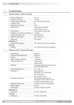
Страница 24: ...mV per rpm as ordered TG 74 d Voltage 20 150 mV per rpm as ordered 11 2 Technical data mechanical design Size flange ø90 mm Protection DIN EN 60529 IP54 T6 Torque 1 5 Ncm Rotor moment of inertia 1 15 kgcm2 Admitted shaft load 60 N axial 80 N radial Materials Housing aluminium die cast alloy Shaft stainless steel Ambient temperature 20 55 C Resistance IEC 60068 2 6 Vibration 10 g 10 2000 Hz IEC 600...

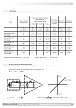
Страница 25: ...nmax U0 mV rpm RL kΩ RL kΩ RL kΩ nmax rpm RA 20 C Ω LA mH EExGP0 2 L 14 TG74 2d 20 0 3 1 2 2 2 8000 9 2 45 EExGP0 2 L 5 TG74 4d 40 1 2 4 8 8 6 8000 38 170 EExGP0 2 L 4 TG74 6d 60 2 7 11 15 7000 86 390 EExGP0 2 L 3 TG74 10d 100 7 5 15 4200 235 1080 EExGP0 2 L 1 TG74 15d 150 16 2800 575 2420 Superimposed ripple for τRC 0 7 ms 0 6 peak peak 0 2 rms 11 4 Replacement switching diagram U n U0 n U0 n for...

Страница 26: ...dard s EN 61000 6 2 2005 EN 61000 6 3 2007 A1 2011 EN 50581 2012 Norme s EN 60034 1 2010 Cor 2010 EN 60034 5 2005 A1 2007 EN 60034 7 1993 A1 2001 EN 60664 1 2007 Konformitätsbewertungsstelle TÜV NORD Cert Conformity assessment center Am TÜV 1 Centre d évaluation et de mise en conformité 30519 Hannover EU Baumusterprüfbescheinigung TÜV 03 ATEX 2201 X EU type examination certificate Klicken Sie hier...

Страница 27: ...MB053 11055655 Baumer_EEXGP02 TG74D_II_DE EN 18A1 ...

Страница 28: ...Originalsprache der Anleitung ist Deutsch Technische Änderungen vorbehalten Original language of this instruction is German Technical modifications reserved Baumer Hübner GmbH P O Box 12 69 43 10609 Berlin Germany Phone 49 0 30 69003 0 Fax 49 0 30 69003 104 info baumerhuebner com www baumer com motion ...

Отзывы: