AW00136902000
BCON Interface
Basler dart BCON
33
5.2.2
Data Serialization and Timing
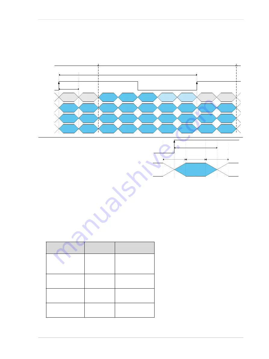
BCON data output is serialized using up to 28 bits on up to four data lanes (X0 to X3).
Two bits are reserved for the output signals (Output 0 and Output 1).
They are always transmitted on data lane X0 at position 0 and 1.
Another two bits are reserved for the synchronization signals (FVal and LVal).
They are always transmitted on data lane X0 at position 2 and 3.
The remaining 24 bits are reserved for the image data channel including frame information,
pixel data, and line checksums.
The actual number of bits and active data lanes used depends on the data being transmitted:
Data Transmitted
Bits Used
Data Lanes Active
Frame information
8-bit pixel data
8-bit checksum
Bit 0 - Bit 7
X0, X1
12-bit pixel data
12-bit checksum
Bit 0 - Bit 11
X0, X1, X2
16-bit pixel data
16-bit checksum
Bit 0 - Bit 15
X0, X1, X2
24-bit pixel data
24-bit checksum
Bit 0 - Bit 23
X0, X1, X2, X3
Table 14: Data Channel Usage
Bit 2
Bit 1
Bit 0
FVal
Output 1
(Line 2)
LVal
Output 0
(Line 1)
X0
Bit 9
Bit 8
Bit 7
Bit 6
Bit 4
Bit 5
Bit 3
X1
Bit 16
Bit 15
Bit 14
Bit 13
Bit 11
Bit 12
Bit 10
X2
Bit 23
Bit 22
Bit 21
Bit 20
Bit 18
Bit 19
Bit 17
X3
WordClk
t
WDV
T
WordClk
T
BitClk
Name
Min
Max
t
WDV
*
Time WordClk to DataValid
-300 ps
300 ps
t
DV
*
Time DataValid
1100 ps
6542 ps
T
BitClk
Period of BitClock
1/7 T
WordClk
X0
...
X3
WordClk
-300ps
300ps
t
WDV
Bit x+1
Bit x
T
BitClk
Bit x-1
Output 1
(Line 2)
Output 0
(Line 1)
Bit 4
Bit 3
Bit 11
Bit 10
Bit 18
Bit 17
Clock cycle n+1
Clock cycle n
t
DV
MSB
LSB
* Actual t
WDV
and t
DV
depend on T
BitClk
. The given values are only
valid on the camera side. Delays due to cable length, cable skew,
and grabber layout are not taken into account.
Fig. 21: BCON Serialization and Timing