


9365200990 Rev F
BE1-CDS240 Testing and Maintenance
13-7
Step 3: To verify that all inputs have been detected, transmit the command RG-INPUT to retrieve
INPUT (12345678) information. Or, alternatively, transmit the command RG-STAT and review
the response at the tail end of the line INPUT (12345678). You may also view the input status
on HMI Screen 1.4.1, \STAT\OPER\INPUT.
Step 4:
Transmit the commands ACCESS=, CS-OUT=ENA, CO-OUT=ENA, EXIT and YES to enable
the output control override capability of the relay in order to pulse each output contact.
Step 5:
From the HMI keypad, navigate to the Screen \CTRL\OUT (Output Control Override) to
override control of the outputs via the keypad.
Step 6:
Once you have accessed the screen, press the
Edit
pushbutton. Select an output to override
by using the
LEFT/RIGHT
arrow pushbuttons. Once selected, use the
UP/DOWN
arrow
pushbuttons to choose the type of action (P, 1 or 0) for the selected contact output. Select the
pulse (P) action for the alarm contact (A). Pressing the
Edit
pushbutton again will force the
alarm output contact action.
Step 7:
Verify that the sequence of events recorder logged the events by sending the command RS-2
to the relay (requesting the last two events it logged). The close-open pulse action should be
listed as two separate events.
Step 8:
Repeat Step 6 for all desired output contacts and then verify that the sequence of events
recorder logged the events.
Current Circuit Verification
Purpose:
To verify that the relay internal CT circuits accurately measure currents and polarities.
Reference Commands:
M-I, SG-TARG, SG-TRIGGER, RS
For all tests in this section, ASCII metering commands, HMI Metering and the
Metering
Screen of
BESTCOMS include angles for each current and voltage quantity. The zero reference for current and
voltage angle measurement is based on the following:
When voltage and current are applied to the relay, VA is the 0° reference for all angle
measurements (VAB for 3-wire connections).
In the absence of phase A or AB voltage, winding 1 A-phase current, IA1 is the 0° reference for
all angle measurements. In the absence of phase A or AB voltage and IA1, winding 2 A-phase
current, IA2 is the 0° reference for all angle measurements, and so on through IA4 for a 4-winding
relay.
In the absence of all other quantities, the calculated positive sequence current (I1) derived from
the CT’s associated with a specific transformer winding becomes the 0° reference for all angle
measurements.
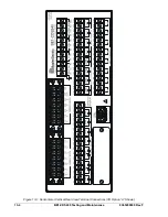
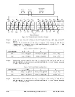
Step1:
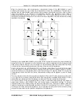
Connect a single-phase current source between Terminals A1 (polarity) and A25 (non-
polarity). Jumper A1 to 3, 4 to 5, 6 to 7, 8 to 9, 10 to 11, 12 to 13, 14 to 16, 15 to 18, 17 to 20,
19 to 22, and 21 to 24. Note that CT circuits 3 and 4 polarities are reversed. Refer to Figure
13-2 for connections.
Содержание BE1-CDS240
Страница 1: ...INSTRUCTION MANUAL FOR CURRENT DIFFERENTIAL SYSTEM BE1 CDS240 Publication 9365200990 Revision F 12 08 ...
Страница 2: ......
Страница 8: ...vi BE1 CDS240 Introduction 9365200990 Rev F This page intentionally left blank ...
Страница 38: ...1 28 BE1 CDS240 General Information 9365200990 Rev F This page intentionally left blank ...
Страница 40: ...ii BE1 CDS240 Quick Start 9365200990 Rev F This page intentionally left blank ...
Страница 74: ...3 22 BE1 CDS240 Input and Output Functions 9365200990 Rev F This page intentionally left blank ...
Страница 152: ...ii BE1 CDS240 Metering 9365200990 Rev F This page intentionally left blank ...
Страница 208: ...ii BE1 CDS240 BESTlogic Programmable Logic 9365200990 Rev F This page intentionally left blank ...
Страница 210: ...Figure 7 1 BESTlogic Function Blocks page 1 of 5 7 2 BE1 CDS240 BESTlogic Programmable Logic 9365200990 Rev F ...
Страница 211: ...Figure 7 2 BESTlogic Function Blocks page 2 of 5 9365200990 Rev F BE1 CDS240 BESTlogic Programmable Logic 7 3 ...
Страница 212: ...Figure 7 3 BESTlogic Function Blocks page 3 of 5 7 4 BE1 CDS240 BESTlogic Programmable Logic 9365200990 Rev F ...
Страница 213: ...Figure 7 4 BESTlogic Function Blocks page 4 of 5 9365200990 Rev F BE1 CDS240 BESTlogic Programmable Logic 7 5 ...
Страница 214: ...Figure 7 5 BESTlogic Function Blocks page 5 of 5 7 6 BE1 CDS240 BESTlogic Programmable Logic 9365200990 Rev F ...
Страница 222: ...7 14 BE1 CDS240 BESTlogic Programmable Logic 9365200990 Rev F This page intentionally left blank ...
Страница 226: ...iv BE1 CDS240 Application 9365200990 Rev F This page intentionally left blank ...
Страница 238: ...Figure 8 3 Typical One line Diagram for CDS240 BA87 B BE 8 12 BE1 CDS240 Application 9365200990 Rev F ...
Страница 262: ...Figure 8 11 Typical One line Diagram for CDS240 BSBU A BE 8 36 BE1 CDS240 Application 9365200990 Rev F ...
Страница 286: ...ii BE1 CDS240 Security 9365200990 Rev F This page intentionally left blank ...
Страница 290: ...9 4 BE1 CDS240 Security 9365200990 Rev F This page intentionally left blank ...
Страница 292: ...ii BE1 CDS240 Human Machine Interface 9365200990 Rev F This page intentionally left blank ...
Страница 296: ...Figure 10 4 BE1 CDS240 Menu Tree Control Branch 10 4 BE1 CDS240 Human Machine Interface 9365200990 Rev F ...
Страница 298: ...Figure 10 6 BE1 CDS240 Menu Tree Reports Branch 10 6 BE1 CDS240 Human Machine Interface 9365200990 Rev F ...
Страница 300: ...Figure 10 8 BE1 CDS240 Menu Tree Protection Branch 2 of 2 10 8 BE1 CDS240 Human Machine Interface 9365200990 Rev F ...
Страница 301: ... Figure 10 9 BE1 CDS240 Menu Tree General Settings Branch 9365200990 Rev F BE1 CDS240 Human Machine Interface 10 9 ...
Страница 306: ...10 14 BE1 CDS240 Human Machine Interface 9365200990 Rev F This page intentionally left blank ...
Страница 308: ...ii BE1 CDS240 ASCII Command Interface 9365200990 Rev F This page intentionally left blank ...
Страница 342: ...11 34 BE1 CDS240 ASCII Command Interface 9365200990 Rev F This page intentionally left blank ...
Страница 349: ...Figure 12 5 Horizontal Rack Mount Front View 9365200990 Rev F BE1 CDS240 Installation 12 5 ...
Страница 351: ...Figure 12 8 Vertical Panel Mount L size Front View 9365200990 Rev F BE1 CDS240 Installation 12 7 ...
Страница 361: ...Figure 12 17 Typical DC Connection Diagrams 9365200990 Rev F BE1 CDS240 Installation 12 17 ...
Страница 365: ...Figure 12 23 BE1 CDS240 Percentage Differential Bus Protection 9365200990 Rev F BE1 CDS240 Installation 12 21 ...
Страница 372: ...12 28 BE1 CDS240 Installation 9365200990 Rev F This page intentionally left blank ...
Страница 468: ...13 92 BE1 CDS240 Testing and Maintenance 9365200990 Rev F This page intentionally left blank ...
Страница 512: ...14 42 BE1 CDS240 BESTCOMS Software 9365200990 Rev F This page intentionally left blank ...
Страница 514: ...ii BE1 CDS240 Time Overcurrent Characteristic Curves 9365200990 Rev F This page intentionally left blank ...
Страница 538: ...ii BE1 CDS240 Overexcitation 24 Inverse Time Curves 9365200990 Rev F This page intentionally left blank ...
Страница 544: ...ii BE1 CDS240 Terminal Communication 9365200990 Rev F This page intentionally left blank ...
Страница 550: ...ii BE1 CDS240 Settings Calculations 9365200990 Rev F This page intentionally left blank ...
Страница 578: ...D 28 BE1 CDS240 Settings Calculations 9365200990 Rev F This page intentionally left blank ...
Страница 579: ......
Страница 580: ...ROUTE 143 BOX 269 HIGHLAND IL 62249 USA http www basler com info basler com PHONE 1 618 654 2341 FAX 1 618 654 2351 ...


