


Style Number and Serial Number Verification
Purpose:
To verify that the BE1-CDS240 relay model number, style number, and current software
program version matches the unit/unit labels.
Reference Commands:
RG-VER
Step 1:
Through any communications port, transmit the command RG-VER. The BE1-CDS240 relay
should respond with the model number, style number, application program version and date,
DSP program version and date, boot program version and date, and the relay serial number.
Verify that all reported data is current, appropriate and matches the label on the relay front
panel.
IRIG Verification
Purpose:
To verify that the BE1-CDS240 relay acquires and updates IRIG time and date information.
Reference Commands:
RG-DATE, RG-TIME
Step 1:
Connect a suitable IRIG source to relay terminals B4 and B5.
Step 2:
Upon receiving the IRIG signal, the relay clock will be updated with the current time, day, and
month. Verify this on Screen \STAT\SCRNS\SCRN on the front panel human-machine
interface (HMI) or by sending the RG-TIME and RG-DATE commands to the relay through any
communications port.
NOTE
The following tests may be skipped if it is critical to expedite the installation of
this device. The commissioning tests later in this section overlap these tests and
will verify proper contact sensing input and control output changes.
Contact Sensing Inputs and Control Outputs
Purpose:
To verify that the BE1-CDS240 relay senses hardware inputs and activates contact outputs.
Reference Commands:
ACCESS, CO-OUT, CS-OUT, EXIT, RG-STAT
NOTE
Each BE1-CDS240 relay is delivered with the eight sensing jumpers installed for
operation in the higher end of the control voltage range. For contact sensing
inputs at the lower end of the control voltage range, change the jumpers to the
Low position or completely remove the jumper. For more information see Section
12,
Installation, Contact Sensing Input Jumpers
.
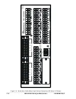
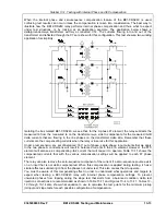
Step 1: Verify that the position of the contact-sensing jumpers is correct before applying wetting
voltage to any input contacts. The number of inputs is dependent of the relay style number.
The “A” option has 12 and the “E” option has 8. (See Section 1,
General Information
, Figure 1-
8.) The “E” style option is used as an example.
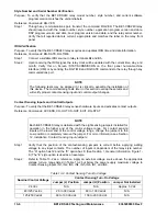
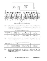
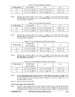
Step 2:
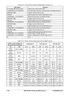
Refer to Table 13-2 as a reference. Apply an external voltage source above the appropriate
voltage turn-on range listed in Table 13-2 but below the power supply maximum voltage to
Contact Sensing Inputs IN1, IN2, IN3, IN4, IN5, IN6, IN7, and IN8.
Table 13-2. Contact Sensing Turn-On Voltage
Contact Sensing Turn-On Voltage
Nominal Control Voltage
Jumper (L) Position
Jumper (H) Position
Jumper Not Installed
24 Vdc
N/A
N/A
Approx. 5 Vdc
48/125 Vac/dc
26 to 38 Vac/dc
69 to 100 Vac/dc
N/A
125/250 Vac/dc
69 to 100 Vac/dc
138 to 200 Vac/dc
N/A
13-6
BE1-CDS240 Testing and Maintenance
9365200990 Rev F
Содержание BE1-CDS240
Страница 1: ...INSTRUCTION MANUAL FOR CURRENT DIFFERENTIAL SYSTEM BE1 CDS240 Publication 9365200990 Revision F 12 08 ...
Страница 2: ......
Страница 8: ...vi BE1 CDS240 Introduction 9365200990 Rev F This page intentionally left blank ...
Страница 38: ...1 28 BE1 CDS240 General Information 9365200990 Rev F This page intentionally left blank ...
Страница 40: ...ii BE1 CDS240 Quick Start 9365200990 Rev F This page intentionally left blank ...
Страница 74: ...3 22 BE1 CDS240 Input and Output Functions 9365200990 Rev F This page intentionally left blank ...
Страница 152: ...ii BE1 CDS240 Metering 9365200990 Rev F This page intentionally left blank ...
Страница 208: ...ii BE1 CDS240 BESTlogic Programmable Logic 9365200990 Rev F This page intentionally left blank ...
Страница 210: ...Figure 7 1 BESTlogic Function Blocks page 1 of 5 7 2 BE1 CDS240 BESTlogic Programmable Logic 9365200990 Rev F ...
Страница 211: ...Figure 7 2 BESTlogic Function Blocks page 2 of 5 9365200990 Rev F BE1 CDS240 BESTlogic Programmable Logic 7 3 ...
Страница 212: ...Figure 7 3 BESTlogic Function Blocks page 3 of 5 7 4 BE1 CDS240 BESTlogic Programmable Logic 9365200990 Rev F ...
Страница 213: ...Figure 7 4 BESTlogic Function Blocks page 4 of 5 9365200990 Rev F BE1 CDS240 BESTlogic Programmable Logic 7 5 ...
Страница 214: ...Figure 7 5 BESTlogic Function Blocks page 5 of 5 7 6 BE1 CDS240 BESTlogic Programmable Logic 9365200990 Rev F ...
Страница 222: ...7 14 BE1 CDS240 BESTlogic Programmable Logic 9365200990 Rev F This page intentionally left blank ...
Страница 226: ...iv BE1 CDS240 Application 9365200990 Rev F This page intentionally left blank ...
Страница 238: ...Figure 8 3 Typical One line Diagram for CDS240 BA87 B BE 8 12 BE1 CDS240 Application 9365200990 Rev F ...
Страница 262: ...Figure 8 11 Typical One line Diagram for CDS240 BSBU A BE 8 36 BE1 CDS240 Application 9365200990 Rev F ...
Страница 286: ...ii BE1 CDS240 Security 9365200990 Rev F This page intentionally left blank ...
Страница 290: ...9 4 BE1 CDS240 Security 9365200990 Rev F This page intentionally left blank ...
Страница 292: ...ii BE1 CDS240 Human Machine Interface 9365200990 Rev F This page intentionally left blank ...
Страница 296: ...Figure 10 4 BE1 CDS240 Menu Tree Control Branch 10 4 BE1 CDS240 Human Machine Interface 9365200990 Rev F ...
Страница 298: ...Figure 10 6 BE1 CDS240 Menu Tree Reports Branch 10 6 BE1 CDS240 Human Machine Interface 9365200990 Rev F ...
Страница 300: ...Figure 10 8 BE1 CDS240 Menu Tree Protection Branch 2 of 2 10 8 BE1 CDS240 Human Machine Interface 9365200990 Rev F ...
Страница 301: ... Figure 10 9 BE1 CDS240 Menu Tree General Settings Branch 9365200990 Rev F BE1 CDS240 Human Machine Interface 10 9 ...
Страница 306: ...10 14 BE1 CDS240 Human Machine Interface 9365200990 Rev F This page intentionally left blank ...
Страница 308: ...ii BE1 CDS240 ASCII Command Interface 9365200990 Rev F This page intentionally left blank ...
Страница 342: ...11 34 BE1 CDS240 ASCII Command Interface 9365200990 Rev F This page intentionally left blank ...
Страница 349: ...Figure 12 5 Horizontal Rack Mount Front View 9365200990 Rev F BE1 CDS240 Installation 12 5 ...
Страница 351: ...Figure 12 8 Vertical Panel Mount L size Front View 9365200990 Rev F BE1 CDS240 Installation 12 7 ...
Страница 361: ...Figure 12 17 Typical DC Connection Diagrams 9365200990 Rev F BE1 CDS240 Installation 12 17 ...
Страница 365: ...Figure 12 23 BE1 CDS240 Percentage Differential Bus Protection 9365200990 Rev F BE1 CDS240 Installation 12 21 ...
Страница 372: ...12 28 BE1 CDS240 Installation 9365200990 Rev F This page intentionally left blank ...
Страница 468: ...13 92 BE1 CDS240 Testing and Maintenance 9365200990 Rev F This page intentionally left blank ...
Страница 512: ...14 42 BE1 CDS240 BESTCOMS Software 9365200990 Rev F This page intentionally left blank ...
Страница 514: ...ii BE1 CDS240 Time Overcurrent Characteristic Curves 9365200990 Rev F This page intentionally left blank ...
Страница 538: ...ii BE1 CDS240 Overexcitation 24 Inverse Time Curves 9365200990 Rev F This page intentionally left blank ...
Страница 544: ...ii BE1 CDS240 Terminal Communication 9365200990 Rev F This page intentionally left blank ...
Страница 550: ...ii BE1 CDS240 Settings Calculations 9365200990 Rev F This page intentionally left blank ...
Страница 578: ...D 28 BE1 CDS240 Settings Calculations 9365200990 Rev F This page intentionally left blank ...
Страница 579: ......
Страница 580: ...ROUTE 143 BOX 269 HIGHLAND IL 62249 USA http www basler com info basler com PHONE 1 618 654 2341 FAX 1 618 654 2351 ...


