background image

9310200990 Rev G 

BE1-79A Testing 

6-5 

POWER HOLDUP CIRCUIT TESTING 

Power holdup circuit testing applies only to BE1-79 relays with part numbers 9310200101 and 
9310200201. 

Part Numbers 9310200101 and 9310200201 

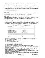
Remove 120 Vac operating power from terminals 5 and 6. Measure the time from when the operating 
power is removed until the RS contacts (terminals 9 and 10) close. The time should be 1.3 seconds or 
greater. 

TROUBLESHOOTING TIPS 

The front panel LED indicators will annunciate certain conditions that will inhibit the BE1-79A relay from 
providing reclose protection. 

Blinking LEDs 

This annunciation indicates low or incorrect relay input voltage. Verify proper contact sensing jumper 
selection. 

All LEDs On 

This annunciation indicates an EEPROM error or recent cycling of relay operating power. 

Содержание BE1-79A

Страница 1: ...INSTRUCTION MANUAL FOR RECLOSING RELAY BE1 79A Publication 9310200990 Revision G 02 08...

Страница 2: ......

Страница 3: ...dicators Functional Description Installation Maintenance WARNING To avoid personal injury or equipment damage only qualified personnel should perform the procedures in this manual NOTE Be sure that th...

Страница 4: ...tion The availability and design of all features and options are subject to modification without notice Should further information be required contact Basler Electric BASLER ELECTRIC ROUTE 143 BOX 269...

Страница 5: ...06 98 Communication was made consistent with other Basler products by adding line feeds to ASCII data returned by the relay 1 02 XX 12 97 Initial release of part number 9310200200 1 01 XX 07 97 Initia...

Страница 6: ...5 Added troubleshooting tips to Section 6 Moved contents of Section 7 to Section 1 and deleted Section 7 Added Appendix A RS Contact Application Added Appendix B Terminal Communication E 04 03 Added...

Страница 7: ...FORMATION 1 1 SECTION 2 CONTROLS AND INDICATORS 2 1 SECTION 3 FUNCTIONAL DESCRIPTION 3 1 SECTION 4 COMMUNICATION COMMANDS 4 1 SECTION 5 INSTALLATION AND CONFIGURATION 5 1 SECTION 6 TESTING 6 1 APPENDI...

Страница 8: ...vi BE1 79A Introduction 9310200990 Rev G This page intentionally left blank...

Страница 9: ...tion 1 1 Power Holdup Circuit 1 1 PRIMARY APPLICATION 1 2 SPECIFICATIONS 1 2 Reclose Timers 1 2 3 and 4 1 2 Reset Timers 1 2 3 4 and Final 1 2 Lockout Timer 1 2 RS Set and Reset Timers 1 2 Communicati...

Страница 10: ...ii BE1 79A General Information 9310200990 Rev G This page intentionally left blank...

Страница 11: ...A maximum of four automatic reclosures A maximum of four automatic resets Lockout function Selectable instantaneous or delayed first reclosure Selectable internal or external instantaneous jumper Sel...

Страница 12: ...ers 1 2 3 and 4 Range 0 to 300 seconds Increments 0 1 second Accuracy 20 milliseconds 1 typical 50 milliseconds 1 maximum Reset Timers 1 2 3 4 and Final Range 0 to 300 seconds Increments 0 1 seconds A...

Страница 13: ...rd Surge Withstand Capability SWC Tests for Protective Relays and Relay Systems The RS 232 Serial Communication Port is intended only for periodic use and is not subject to the requirements of IEEE C3...

Страница 14: ...re no preventative maintenance However testing should be performed according to scheduled practices If the relay fails to function properly contact the Technical Support Services department of Basler...

Страница 15: ...2 1 STYLE CONFIGURATION SWITCHES 2 2 INSTANTANEOUS RECLOSE JUMPER SWITCH AND RS CONTACT SWITCH 2 2 Figures Figure 2 1 Front Panel Controls and Indicators 2 1 Figure 2 2 Style Configuration Switches 2...

Страница 16: ...ii BE1 79A Controls and Indicators 9310200990 Rev G This page intentionally left blank...

Страница 17: ...y settings can be read or changed Communication with the BE1 79A uses a simple ASCII command language B Power LED A lit Power LED indicates that operating power is applied to the relay C Identificatio...

Страница 18: ...placed in the A position Figure 2 2 Style Configuration Switches INSTANTANEOUS RECLOSE JUMPER SWITCH AND RS CONTACT SWITCH Two switches on the right side of the relay cradle select either internal or...

Страница 19: ...9310200990 Rev G BE1 79A Controls and Indicators 2 3 Figure 2 3 Instantaneous Reclose Jumper Switch and RS Contact Selection Switch...

Страница 20: ...2 4 BE1 79A Controls and Indicators 9310200990 Rev G This page intentionally left blank...

Страница 21: ...s 3 8 Figures Figure 3 1 Function Block Diagram 3 1 Figure 3 2 Relay Interconnections for ACR11A Applications 3 5 Figure 3 3 Relay Interconnections for ACR11B Applications 3 6 Figure 3 4 Power Up Flow...

Страница 22: ...ii BE1 79A Functional Description 9310200990 Rev G This page intentionally left blank...

Страница 23: ...The BE1 79A 200 and 201 consist of a draw out cradle assembly with a steel and phenolic case The case has the same overall dimensions as a Basler Electric or General Electric S1 case CIRCUIT OPERATIO...

Страница 24: ...pends on the operating configuration of the relay Tables 3 2 and 3 3 describe the function of each contact sensing input for each relay configuration The GE nomenclature used for each input is provide...

Страница 25: ...he reset switch performs the same function as the manual clutch release on the General Electric ACR11 relay Operating power must be applied to terminals 5 and 6 in order for a reset to occur Serial Co...

Страница 26: ...tarily when voltage is sensed at input V4 and the relay is in a reset condition Z2 E6 C2 13 14 Closed during reset and open when voltage at input V3 is sensed During a reclose sequence C2 remains open...

Страница 27: ...power removed from the relay Figure 3 2 shows the relay configured for an ACR11A application Figure 3 3 shows the relay configured for an ACR11B application with an instantaneous recloser jumper 11 1...

Страница 28: ...C8 V1 V5 V2 V3 V4 C3 C10 C1 C2 C4 C5 C7 C9 S3 S1 S1 S2 S2 S4 INT EXT A B B A C6 B A A B B A D2633 05 07 26 05 NC NO S5 Power Supply RS D E 1 RS mode electronic selector switch SP 79ARS command 1 2 Ca...

Страница 29: ...conditions and the reset delay setting the interval from power application to the resultant state may be from 0 to 300 seconds Reclose Power Up In Reset At Power Up Style Change Prior To Power Up Res...

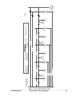
Страница 30: ...y settings after the first reclose to zero When a breaker trip occurs at this point in the reclosing sequence the BE1 79A will time toward lockout An instantaneous first reclose is enabled on BE1 79A...

Страница 31: ...t 180 s 180 s 185 s P0034 01 09 20 05 2nd Breaker Opening 3rd Breaker Opening 4th Breaker Opening 5th Breaker Opening Reclose 2 30 s Reset 1 20 s Reset 2 40 s Reclose 3 50 s Reset 3 60 s Reclose 4 70...

Страница 32: ...Rec 3 Time 52B Issue Reclose Signal 52B Reclose Complete Reset 3 Time 52A Reset Reset Complete Rec 4 0 Perform Lockout 52B Issue Reclose Signal 52B Reclose Complete Reset 4 Time 52A Reset Reset Compl...

Страница 33: ...OF CONTENTS SECTION 4 COMMUNICATION COMMANDS 4 1 INTRODUCTION 4 1 COMMUNICATION PORT PARAMETERS 4 1 ASCII command format 4 1 Command Format 4 1 Command Response Format 4 1 COMMAND DESCRIPTIONS 4 2 Cha...

Страница 34: ...ii BE1 79A Communication Commands 9310200990 Rev G This page intentionally left blank...

Страница 35: ...ot part of the command Separators are used for clarity The separators are not part of the command CMD name n setting x setting x Where Name Command name Refer to Command Descriptions for more informat...

Страница 36: ...to continue using the old settings The CR characters placed after commands represent a carriage return or pressing the Enter key For simplicity they will no longer be shown However each line entered...

Страница 37: ...lf may be used to read all relay settings SP 79A n is used to read a specific setting the S command can be used to make a record of the relay settings after they have been set S command example Obtain...

Страница 38: ...act settings Syntax SP 79ARS mode apply time remove time Comments mode the state of the RS coil and contact which can be D or E for the coil status D de energized RS coil Second NO contact when termin...

Страница 39: ...5 8 Alarm Output 5 8 Reset Switch 5 9 RELAY INSTALLATION 5 9 communication connections and settings 5 9 Communication Connector 5 9 Communication Settings 5 10 Figures Figure 5 1 Overall Dimensions S1...

Страница 40: ...ii BE1 79A Installation and Configuration 9310200990 Rev G This page intentionally left blank...

Страница 41: ...an ACR11B style relay APPLICATION The intended function of the BE1 79A Reclosing Relay is to duplicate an ACR11 recloser with only minor variations To ensure that your BE1 79A relay functions properly...

Страница 42: ...tch RS switch S5 is used to control the RS contact for normally open or normally closed contact configuration Figure 2 2 and 2 3 should be consulted for the location and setting positions of the style...

Страница 43: ...9310200990 Rev G BE1 79A Installation and Configuration 5 3 Figure 5 2 Panel Cutout Dimensions S1 Case...

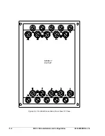
Страница 44: ...5 4 BE1 79A Installation and Configuration 9310200990 Rev G D2588 17 06 05 97 Figure 5 3 Terminal Connections Rear View S1 Case...

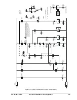
Страница 45: ...9310200990 Rev G BE1 79A Installation and Configuration 5 5 Figure 5 4 Typical Connections for ACR11A Application...

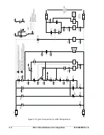
Страница 46: ...5 6 BE1 79A Installation and Configuration 9310200990 Rev G Figure 5 5 Typical Connections for ACR11B Application...

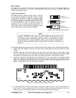
Страница 47: ...circuit board from the relay chassis Take care not to damage any of the circuit board components Observe all electrostatic discharge ESD precautions when handling the circuit board Place the circuit b...

Страница 48: ...instantaneous reclose with no voltage applied at terminals 5 and 6 If this unusual application is employed the user must confirm that voltage is applied to BE1 79A terminals 5 and 6 when a reclose is...

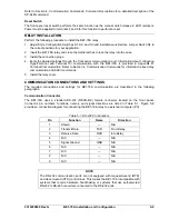
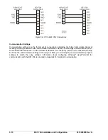
Страница 49: ...ix B Terminal Communication Refer to Section 4 Communication Commands for information about relay communication and ASCII commands 5 Install the relay cover COMMUNICATION CONNECTIONS AND SETTINGS The...

Страница 50: ...two communication terminals The BE1 79A settings are fixed at 9600 8N1 where 9600 is the baud rate 8 is the number of data bits N is the parity none and 1 indicates one stop bit Since the communicatio...

Страница 51: ...6 2 ACR11A Style 6 2 ACR11B Style 6 2 ACR11A and ACR11B Styles 6 2 POWER HOLDUP CIRCUIT TESTING 6 5 Part Numbers 9310200101 and 9310200201 6 5 TROUBLESHOOTING TIPS 6 5 Blinking LEDs 6 5 All LEDs On 6...

Страница 52: ...ii BE1 79A Testing 9310200990 Rev G This page intentionally left blank...

Страница 53: ...unication software to the relay serial port Transmit the settings of Table 6 1 to the relay Table 6 1 Instantaneous Reclose Testing Commands Command Time Between Recloses ACCESS cr N A SP 79A1 0 0 5 0...

Страница 54: ...gs correspond to the illustration of Figure 3 5 Table 6 2 Delayed Reclose Testing Commands Command Time Between Recloses ACCESS cr N A SP 79A1 10 0 20 0 cr 10 0 10 s SP 79A2 30 0 40 0 cr 30 10 20 s SP...

Страница 55: ...Closes opens at time set by user Instantaneous First Reclose Contact closes when terminal 7 is energized Delayed First Reclose External Jumpers BE1 79A 1 2 3 4 5 6 7 8 9 10 11 12 13 14 15 16 17 18 19...

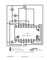
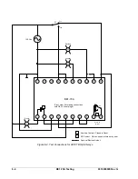
Страница 56: ...5 6 7 8 11 12 13 14 15 16 17 18 19 20 A L1 L2 S1 52A 52B L3 120 Vac A B Auxiliary Contact Closed in Reset Optional Reclose Output Reset Lockout Reclose D2588 09 08 01 05 9 10 B NC NO S5 Front view Fo...

Страница 57: ...erating power is removed until the RS contacts terminals 9 and 10 close The time should be 1 3 seconds or greater TROUBLESHOOTING TIPS The front panel LED indicators will annunciate certain conditions...

Страница 58: ...6 6 BE1 79A Testing 9310200990 Rev G This page intentionally left blank...

Страница 59: ...T OUTPUT STATE A 1 RS CONTACT SETTINGS A 2 Mode D Example A 2 Mode E Example A 2 RS CONTACT EXAMPLE FOR TRANSFORMER LTC BLOCKING A 4 SP 79ARS Mode Selection A 4 SP 79ARS Remove Time Selection A 4 RS C...

Страница 60: ...ii BE1 79A RS Contact Application 9310200990 Rev G This page intentionally left blank...

Страница 61: ...Closes at 145 s E 2 5 145 NO Open Closed Opens at 2 5 s Closes at 145 s Table A 1 Notes SP 79ARS command syntax is SP 79ARS mode apply time remove time Mode D indicates that the RS element is de energ...

Страница 62: ...tact Remove time is reached If operating power is lost at terminals 5 and 6 during this time the NC contact will close as indicated in Table A 1 BE1 79A Power Off When the Remove time expires the NC c...

Страница 63: ...s 185 s P0034 01 09 20 05 2nd Breaker Opening 3rd Breaker Opening 4th Breaker Opening 5th Breaker Opening Reclose 2 30 s Reset 1 20 s Reset 2 40 s Reclose 3 50 s Reset 3 60 s Reclose 4 70 s Reset 4 8...

Страница 64: ...is condition will enable the user to take the necessary steps to prevent the condition from occurring SP 79ARS Remove Time Selection The RS contact Remove time when used for LTC blocking should be lon...

Страница 65: ...AL COMMUNICATION B 1 WINDOWS 2000 XP B 1 Windows Vista B 4 Figures Figure B 1 Connection Description Dialog Box B 1 Figure B 2 Connect To Dialog Box B 2 Figure B 3 COM Properties Dialog Box B 2 Figure...

Страница 66: ...ii BE1 79A Terminal Communication 9310200990 Rev G This page intentionally left blank...

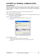
Страница 67: ...lar Step 1 Click Start Highlight Programs Accessories Communication HyperTerminal Step 2 Click HyperTerminal to open the folder Step 3 Select the file or icon labeled Hypertrm or Hypertrm exe Once the...

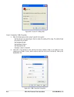
Страница 68: ...that it matches the setting of the relay The default baud rate of the relay is 9 600 Set the Data bits at 8 Set the Parity to None Set the Stop bits at 1 Set Flow control to Xon Xoff b Click OK This c...

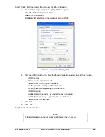
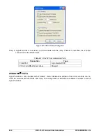
Страница 69: ...the ASCII Setup button Make the following selections using Figure B 5 as a guide ASCII Sending Place a check at Send line ends Place a check at Echo typed characters Set the Line delay setting to 100...

Страница 70: ...d connection for the RS 232 port Table B 1 RS 232 Communication Ports Connection Type Front Port 9 pin female DCE PC to Front RS 232 port cable Straight WINDOWS VISTA HyperTerminal is not provided wit...

Страница 71: ...ROUTE 143 BOX 269 HIGHLAND IL 62249 USA http www basler com info basler com PHONE 1 618 654 2341 FAX 1 618 654 2351...

Отзывы: