37-4
9424200996
Breaker Monitoring
BE1-11
m
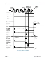
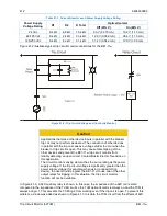
Table 37-2. Legend for Figure 37-3
Locator
Description
A
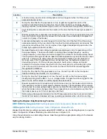
A fault summary report and an oscillograph record are triggered when the Pickup logic
expression becomes true.
B
During the time that the Trip expression is true, targets are logged from each of the
protective functions that reach a trip state. If a protective function is not being used for
tripping purposes, the associated target function can be disabled through BESTCOMS
Plus
.
C
Fault clearing time is calculated as the duration of the time that the Pickup logic expression
is true.
D
Breaker operate time is calculated as the time from when the Trip logic expression becomes
true until the fast current detector senses that the breaker has successfully interrupted the
current in all poles of the breaker.
E
A second oscillographic record is triggered to record the end of the fault if the Pickup logic
expression remains in the true state at the time that the first oscillographic record ends. This
second record will have from ¼ to five cycles of pre-trigger data depending upon when the
Pickup logic expression becomes false.
F
Recorded fault current and voltage magnitudes are displayed on the Targets screen of the
front-panel display. The same information including phase voltage frequency, auxiliary
voltage frequency, and voltage and current angles are recorded in the fault summary report.
The magnitude and angle results are based on data captured two cycles after the trip output
goes true. This two-cycle delay allows the line transients to settle to provide data that is
more accurate. If the Trip expression does not become true, the fault was cleared by a
down-stream device. For these pickup-only events, fault current, voltage, and angle
recorded in the fault summary report will be for the power system cycle ending two cycles
prior to the end of the fault record. This is also the case if the fault record was triggered
through BESTCOMS
Plus
.
G
During the time that the Pickup expression is true, the red Trip LED on the front panel
flashes indicating that the BE1-11
m
is picked up.
H
During the time the Trip expression is true, the red Trip
LED on the front panel lights
steadily indicating that the BE1-11
m
is in a tripped state. If targets have been logged for the
fault, the Trip LED is sealed in until the targets have been reset.
I
Breaker operations and interruption duty functions are driven by the breaker status function.
The operations counter is incremented on breaker opening. The magnitudes of the currents
that are used for accumulating breaker duty are recorded for the power system cycle ending
when the breaker status changes state. Thus, breaker duty is accumulated every time that
the breaker opens even if it is not opening under fault.
J
Setting group changes are blocked when the Pickup expression is true to prevent protective
functions from being reinitialized with new operating parameters while a fault is occurring.
Setting the Breaker Duty Monitoring Function
BESTCOMS
Plus
Navigation Path:
Settings Explorer, Alarm Configuration, Breaker Monitoring
HMI Navigation Path:
Settings Explorer, Alarm Configuration, Breaker Monitor
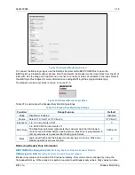
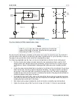
Breaker Duty Monitoring settings are made using BESTCOMS
Plus
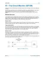
. Use the Settings Explorer to open the
Alarm Configuration, Breaker Monitoring tree branch shown in Figure 37-4.
Using the pull-down menus and settings boxes, make the application-appropriate settings to the breaker
duty monitoring function.
Содержание BE1-11m
Страница 8: ...vi 9424200996 Revision History BE1 11m...
Страница 12: ...x 9424200996 Contents BE1 11m...
Страница 21: ...9424200996 1 9 BE1 11m Introduction Figure 1 1 Style Chart...
Страница 22: ...1 10 9424200996 Introduction BE1 11m...
Страница 40: ...3 6 9424200996 Controls and Indicators BE1 11m Figure 3 3 Front Panel Display Setup Screen...
Страница 53: ...9424200996 5 5 BE1 11m Phase Undervoltage 27P Protection Figure 5 3 Phase Undervoltage Settings Screen...
Страница 54: ...5 6 9424200996 Phase Undervoltage 27P Protection BE1 11m...
Страница 56: ...6 2 9424200996 Negative Sequence Voltage 47 Protection BE1 11m...
Страница 61: ...9424200996 7 5 BE1 11m Phase Overvoltage 59P Protection Figure 7 3 Overvoltage Settings Screen...
Страница 62: ...7 6 9424200996 Phase Overvoltage 59P Protection BE1 11m...
Страница 68: ...8 6 9424200996 Auxiliary Overvoltage 59X Protection BE1 11m...
Страница 80: ...12 4 9424200996 Instantaneous Overcurrent 50 Protection BE1 11m...
Страница 84: ...13 4 9424200996 Breaker Failure 50BF Protection BE1 11m...
Страница 91: ...9424200996 14 7 BE1 11m Inverse Overcurrent 51 Protection Figure 14 4 Inverse Overcurrent Settings Screen...
Страница 92: ...14 8 9424200996 Inverse Overcurrent 51 Protection BE1 11m...
Страница 105: ...9424200996 18 3 BE1 11m Power Factor 55 Protection Figure 18 2 Power Factor Settings Screen...
Страница 106: ...18 4 9424200996 Power Factor 55 Protection BE1 11m...
Страница 110: ...19 4 9424200996 Resistance Temperature Detector 49RTD Protection BE1 11m...
Страница 118: ...20 8 9424200996 Thermal Curve 49TC Protection BE1 11m...
Страница 122: ...22 2 9424200996 Starts per Time Interval 66 Protection BE1 11m...
Страница 124: ...23 2 9424200996 Restart Inhibit Protection BE1 11m...
Страница 130: ...25 4 9424200996 Virtual Control Switches 43 BE1 11m Figure 25 3 Virtual Control Switches Settings Screen...
Страница 140: ...28 4 9424200996 Breaker Control Switch 101 BE1 11m...
Страница 148: ...29 8 9424200996 Setting Groups BE1 11m...
Страница 156: ...30 8 9424200996 Metering BE1 11m Figure 30 11 RTD Meter Screen...
Страница 158: ...31 2 9424200996 Digital Points BE1 11m Figure 31 2 Digital Points Monitor Screen...
Страница 177: ...9424200996 34 5 BE1 11m Motor Reporting Figure 34 9 Learned Motor Data Screen...
Страница 178: ...34 6 9424200996 Motor Reporting BE1 11m...
Страница 184: ...35 6 9424200996 Alarms BE1 11m...
Страница 186: ...36 2 9424200996 Differential Reporting BE1 11m...
Страница 196: ...38 4 9424200996 Demands BE1 11m...
Страница 198: ...39 2 9424200996 Load Profile BE1 11m...
Страница 207: ...9424200996 41 5 BE1 11m Trip Circuit Monitor 52TCM Figure 41 6 Trip Circuit Monitor Settings Screen...
Страница 208: ...41 6 9424200996 Trip Circuit Monitor 52TCM BE1 11m...
Страница 212: ...42 4 9424200996 Fuse Loss 60FL BE1 11m...
Страница 218: ...43 6 9424200996 BESTnet Plus BE1 11m Figure 43 8 Power Quality Page...
Страница 221: ...9424200996 44 3 BE1 11m Mounting Figure 44 3 Case Side Dimensions...
Страница 227: ...9424200996 44 9 BE1 11m Mounting Figure 44 9 Retrofit Mounting Plate Basler P N 9424200073 Part 2...
Страница 235: ...9424200996 45 5 BE1 11m Terminals and Connectors Figure 45 7 Example of Reversed CT Polarity...
Страница 236: ...45 6 9424200996 Terminals and Connectors BE1 11m...
Страница 269: ...9424200996 48 15 BE1 11m BESTlogic Plus Figure 48 4 Logic Page 1 for Default Logic...
Страница 288: ...49 10 9424200996 Communication BE1 11m Figure 49 14 Modbus Mapping Screen...
Страница 301: ...9424200996 51 5 BE1 11m Timekeeping Figure 51 3 Front Panel Circuit Board Backup Battery Location...
Страница 306: ...52 4 9424200996 Device Information BE1 11m...
Страница 314: ...53 8 9424200996 Configuration BE1 11m Figure 53 3 Display Units Screen...
Страница 318: ...54 4 9424200996 Introduction to Testing BE1 11m...
Страница 330: ...56 6 9424200996 Commissioning Testing BE1 11m...
Страница 336: ...58 4 9424200996 Phase Undervoltage 27P Test BE1 11m...
Страница 340: ...59 4 9424200996 Phase Overvoltage 59P Test BE1 11m...
Страница 352: ...60 12 9424200996 Auxiliary Overvoltage 59X Test BE1 11m...
Страница 360: ...61 8 9424200996 Frequency 81 Test BE1 11m...
Страница 364: ...62 4 9424200996 Instantaneous Undercurrent 37 Test BE1 11m...
Страница 376: ...63 12 9424200996 Instantaneous Overcurrent 50 Test BE1 11m...
Страница 396: ...65 16 9424200996 Inverse Overcurrent 51 Test BE1 11m...
Страница 408: ...67 6 9424200996 Power 32 Test BE1 11m...
Страница 412: ...68 4 9424200996 Loss of Excitation Reverse Var Based 40Q Test BE1 11m...
Страница 426: ...70 10 9424200996 Thermal Curve 49TC Test BE1 11m...
Страница 432: ...72 4 9424200996 Starts per Time Interval 66 Test BE1 11m...
Страница 436: ...73 4 9424200996 Restart Inhibit Test BE1 11m...
Страница 440: ...74 4 9424200996 Virtual Control Switches 43 Test BE1 11m...
Страница 450: ...75 10 9424200996 Logic Timers 62 Test BE1 11m...
Страница 464: ...79 8 9424200996 Troubleshooting BE1 11m...
Страница 480: ...80 16 9424200996 Specifications BE1 11m...
Страница 496: ...82 8 9424200996 Time Curve Characteristics BE1 11m Figure 82 3 Time Characteristic Curve A Standard Inverse BS 142...
Страница 497: ...9424200996 82 9 BE1 11m Time Curve Characteristics Figure 82 4 Time Characteristic Curve A1 Inverse IEC 60255 151 Ed 1...
Страница 504: ...82 16 9424200996 Time Curve Characteristics BE1 11m Figure 82 11 Time Characteristic Curve G Long Time Inverse BS 142...
Страница 507: ...9424200996 82 19 BE1 11m Time Curve Characteristics Figure 82 14 Time Characteristic Curve B Very Inverse BS 142...
Страница 512: ...82 24 9424200996 Time Curve Characteristics BE1 11m Figure 82 19 Time Characteristic Curve C Extremely Inverse BS 142...
Страница 570: ...84 26 9424200996 Settings Calculation Examples BE1 11m Figure 84 31 Time vs Current and Thermal Limit Curves...
Страница 597: ...9424200996 84 53 BE1 11m Settings Calculation Examples Figure 84 67 Logic Page 1 Unchanged from Induction Motor Default...
Страница 598: ...84 54 9424200996 Settings Calculation Examples BE1 11m Figure 84 68 Logic Page 2 Unbalance Trip and Alarm Added...
Страница 599: ...9424200996 84 55 BE1 11m Settings Calculation Examples Figure 84 69 Logic Page 3 Power Factor 55 Added...
Страница 600: ...84 56 9424200996 Settings Calculation Examples BE1 11m Figure 84 70 Logic Page 4 Part 1...
Страница 602: ...84 58 9424200996 Settings Calculation Examples BE1 11m...
Страница 608: ...85 6 9424200996 BESTCOMSPlus Settings Loader Tool BE1 11m...
Страница 609: ......

