Operation and Installation Manual PBTC-200
21-54C3-7D0001/-
04/2021-EHT-441168
Notice:
Technical data subject to change without notice.
No claims for damage arising from alternations, errors or misprints shall be allowed.
Page 19 / 45
9
Installation and Assembly
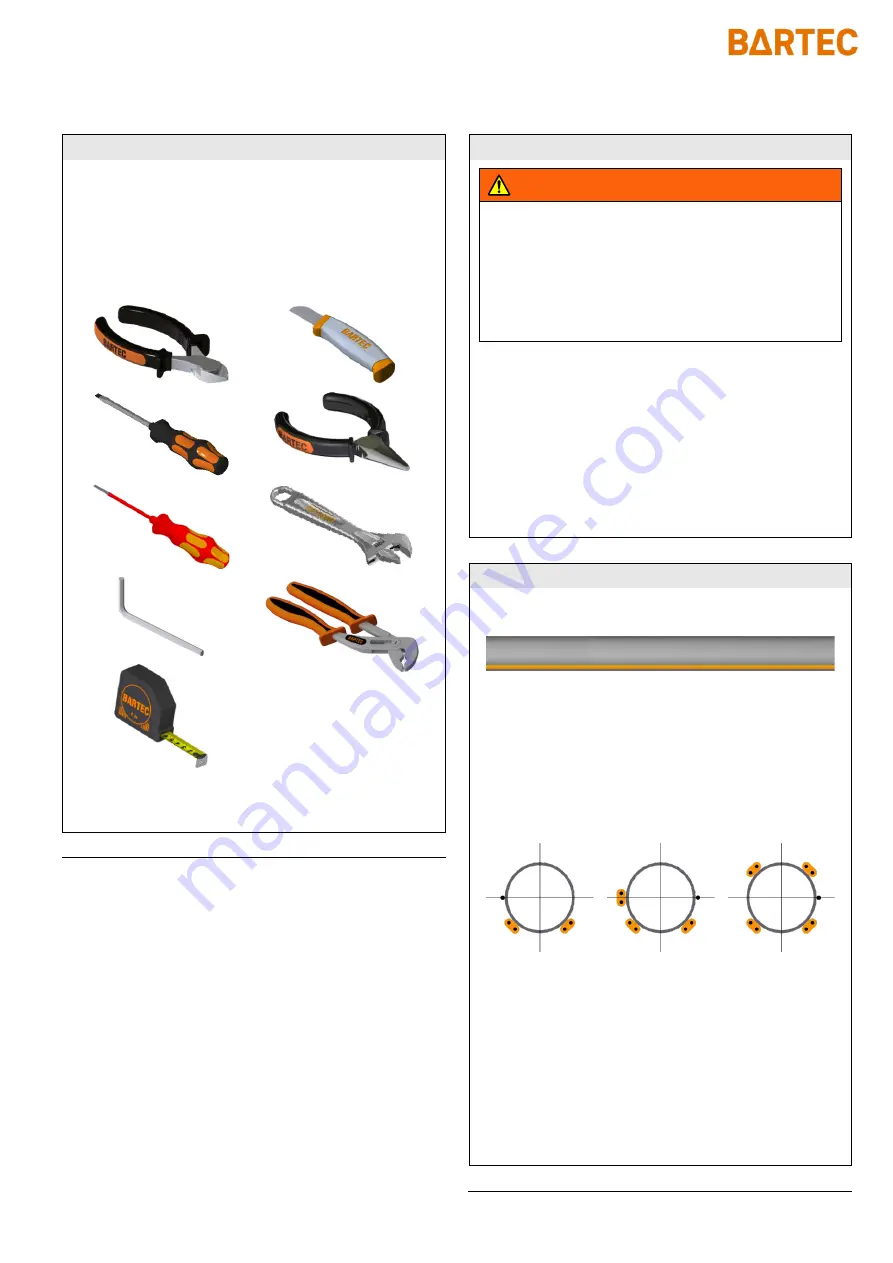
Required Tools / Equipment
The following tools and equipment are required for installa-
tion of the PBTW-200-E:
Wire cutters
Flat screwdriver 2,5mm
Flat screwdriver 3,5mm
Electricians screwdriver
4 mm hex wrench
Tape measure
Utility knife
Needle-nose pliers (2x)
Adjustable wrench (2x)
Tongue and groove pliers
Safety Instructions
WARNING
Fire and electric shock hazard from electrical trace
heating system
Risk of injury due to electric voltage
When starting installation and maintenance work, dis-
connect all circuits from the power supply and check
that there are voltage-free!
Operate electrical trace heating systems with residual
current protection device!
Only one heating cable per junction box
Only connect heating cable types approved for this purpose
Observe maximum permissible heating circuit length
Observe Design Guide for trace heating systems
Observe the project planning documentation of the trace
heating system
Installing the Heating Cable
Install the heating cable in a straight line along the pipe if
possible
If possible, install the heating cable in the lower half of the
pipe, but not at the lowest point
If necessary, return the heating cable loop to the heating
cable at the greatest possible distance
Install the Resistance Temperature Device directly on the
pipe
Install the Resistance Temperature Device in the lower
area of the pipe cross section
Install the Resistance Temperature Device at the greatest
possible distance from the heating cable
Observe additionally required heating cable lengths (as-
sembly of connections, T-branches and end terminations,
each approx. 0.5 m)
Avoid damage to the heating cable and the Resistance
Temperature Device: no bending, pinching or pulling over
sharp edges
2
3
2 x
1
Содержание PBTC-200
Страница 2: ......


