


RDG603A23
–
Issue 20
Page 28 of 84
11. Electrics
CAUTION
•
Do not attach any part, hose or cable to the engine wiring harness. There is a warning
label attached to the harness to remind you of this.
•
Connect the wiring extension harness multi plug to the panel plug and the other end
to the engine.
•
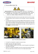
Connect the start battery positive cable to the engine starter motor solenoid terminal.
•
The start motor battery cable must have a cross sectional area of at least 70mm
2
.
•
A 24v 120A alternator should have a minimum cable cross sectional area of 40mm
2
.
•
Connect the domestic battery positive cable to the 120A alternator B+ terminal. This
ensures the 150A alternator charges the start battery. The blue link wire between the
120A Alternator B+ terminal or 15
0A “B+” terminal and the starter motor solenoid
MUST
be removed when the domestic battery is connected.
•
Both the negative battery terminals can be connected to a common earth point.
Note: The 240A alternator is of the insulated earth design and requires a heavy duty earth
cable installed at all times.
12. Electrical Options
DANGER:
ELECTRIC SHOCK RISK!
•
If the engine is fitted with the optional 230V
‘E’ Kit
System, refer to the manual supplied
with it for correct wiring, control box installation and operation.
•
The Shire range can be supplied with other optional additional 12V, 24V or 48V
alternators. This will be supplied fitted but not wired. It is the responsibility of the boat
builder to ensure that this is correctly wired to the boats electrical system.


