R5906788-03
Thor series
49
1.
Before adjusting tilt, make sure the projector is as well-centered with the theatre screen as possible for the
installation area.
2.
Check the degree of screen tilt, or measure this incline with a protractor at the screen.
3.
Tilt the projector to closely match this screen tilt angle as follows:
•
Loosen the nut (reference 1 Image 6-5) on the threaded rod of the four projector feet. Use a 24 mm open
end wrench.
•
Adjust the height of the four legs until the projected image matches the projection port window and the
screen tilt. Use a 17 mm open wrench to adjust the height as illustrated (reference 2 Image 6-5).
•
Secure the leg height by tightening the long nuts (reference 1 Image 6-5) of each projector foot.
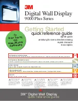
90°
Inclined screen
Image 6-6
CAUTION:
The Thor series may tilt maximum 20° forward and maximum 5° backwards. No tilt is
allowed sideways.
All feet have an adjustment range of 10 cm. The minimum feet height is 8 cm below the bottom of
the projector, the maximum feet height is 18 cm. This correspond with a forward tilt of 6.7° if the
front feet are completely turned in and the back feet turned out.
Barco offers a pedestal for the Thor series projector. This pedestal has height adjustment blocks
which allows extra tilt of 3.3°/block (one block has a height of 5 cm). Maximum stack additional
blocks four high.
6.3 Connecting the hoses with projector and
chillers
What has to be done?
The cooling circuit of the chiller(s) has to be connected with the cooling circuit of the projector. For that hoses
are needed. The length of the hoses depend on the position of the chillers in relation to the projector. The
maximum length is 10 meter!
Depending on the projector model one or two chillers are required! For the Thor series projector one chiller
has to be installed. The Thor+ series needs two chillers.
This procedure assumes that the chiller(s) and projector are already installed.
It is also advised to use the Thor series accessory kit and install the support frames before you
connect the hoses and use the hose shells after connecting the hoses. See the Accessory kit
installation manual for more details.
Содержание Thor Series
Страница 1: ...ENABLING BRIGHT OUTCOMES Installation manual Thor series...
Страница 2: ...Barco NV President Kennedypark 35 8500 Kortrijk Belgium www barco com en support www barco com...
Страница 8: ...R5906788 03 Thor series 8...
Страница 24: ...R5906788 03 Thor series 24 Safety Information...
Страница 26: ...R5906788 03 Thor series 26 Commander Web Commander System overview...
Страница 44: ...R5906788 03 Thor series 44 Installation process...
Страница 68: ...R5906788 03 Thor series 68 Lenses Lens selection...
Страница 78: ...R5906788 03 Thor series 78 Installing a HDD into the ICMP ICMP...
Страница 110: ...R5906788 03 Thor series 110 Starting up...
Страница 122: ...R5906788 03 Thor series 122 Scheimpflug...
Страница 130: ...R5906788 03 Thor series 130 Convergence...
Страница 142: ...R5906788 03 Thor series 142 Preventative maintenance actions...
Страница 160: ...R5906788 03 Thor series 160 Specifications...
Страница 168: ...R5906788 03 Thor series 168 Pin configurations...
Страница 172: ...R5906788 03 Thor series 172 Environmental information...
Страница 176: ...Glossary R5906788 03 Thor series 176...
Страница 181: ...R5906788 03 Thor series 181...
Страница 182: ...Barco NV President Kennedypark 35 8500 Kortrijk Belgium www barco com R5906788 03 07 09 2018...