13. E2 Maintenance
13.29 Ethernet Cable
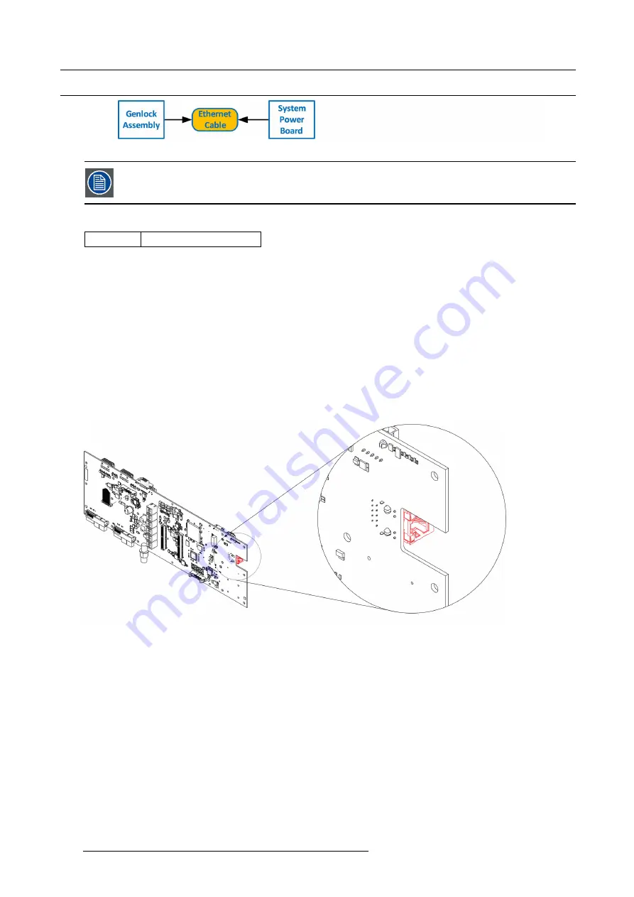
Image 13-74
The Ethernet cable connects the Genlock board to the System Power board. This procedure provides instruc-
tions on how to remove the cable from both sides.
Concerned parts
R767269K
Cable Kit Set
Necessary tools
1 x Phillips Screwdriver #2
How to remove the Ethernet cable
1. Follow the steps detailed in other procedures to remove Ethernet cable from the Genlock assembly.
2. Turn the unit upside down and follow the steps detailed in other procedures to remove the Bottom Panel and the CPU module
from the System-Power board.
3. Remove the USB, VFD, 3RU and 1RU cables that are connected to the System-Power board.
4. Remove the screws that attach the System-Power Board to the standoffs.
5. Lift the System Power Board from the standoffs and
fl
ip it over, but don’t extend it too much.
6. Locate the Ethernet connector and push the locking clip on the Ethernet cable so it can be released from the socket.
Image 13-75
7. Carefully remove the cable from the unit.
How to install the Ethernet Cable
To install the Ethernet Cable follow the same procedure in the reverse order.
400
R5905948 EVENT MASTER DEVICES 17/07/2017
Содержание S3 series
Страница 1: ...Event Master Devices User s Guide R5905948 05 17 07 2017 ...
Страница 9: ...Table of contents Index 531 R5905948 EVENT MASTER DEVICES 17 07 2017 5 ...
Страница 10: ...Table of contents 6 R5905948 EVENT MASTER DEVICES 17 07 2017 ...
Страница 20: ...2 Safety 16 R5905948 EVENT MASTER DEVICES 17 07 2017 ...
Страница 66: ...4 Hardware orientation 62 R5905948 EVENT MASTER DEVICES 17 07 2017 ...
Страница 90: ...5 Front Panel Menu orientation 86 R5905948 EVENT MASTER DEVICES 17 07 2017 ...
Страница 264: ...8 Updating firmware 260 R5905948 EVENT MASTER DEVICES 17 07 2017 ...
Страница 268: ...9 General operation example Image 9 3 264 R5905948 EVENT MASTER DEVICES 17 07 2017 ...
Страница 285: ...9 General operation example Image 9 25 R5905948 EVENT MASTER DEVICES 17 07 2017 281 ...
Страница 288: ...9 General operation example 284 R5905948 EVENT MASTER DEVICES 17 07 2017 ...
Страница 316: ...10 Controller orientation 312 R5905948 EVENT MASTER DEVICES 17 07 2017 ...
Страница 326: ...11 Controller Configuration 322 R5905948 EVENT MASTER DEVICES 17 07 2017 ...
Страница 352: ...12 Controller Operation 348 R5905948 EVENT MASTER DEVICES 17 07 2017 ...
Страница 356: ...13 E2 Maintenance 13 2 Process Overview Flow chart Image 13 2 352 R5905948 EVENT MASTER DEVICES 17 07 2017 ...
Страница 417: ...13 E2 Maintenance Disregard the heatsink from the spare kit R5905948 EVENT MASTER DEVICES 17 07 2017 413 ...
Страница 418: ...13 E2 Maintenance 414 R5905948 EVENT MASTER DEVICES 17 07 2017 ...
Страница 422: ...14 S3 Maintenance 14 2 Process Overview Flow chart Image 14 2 418 R5905948 EVENT MASTER DEVICES 17 07 2017 ...
Страница 488: ...16 EC 200 Maintenance 484 R5905948 EVENT MASTER DEVICES 17 07 2017 ...
Страница 494: ...17 Environmental information 490 R5905948 EVENT MASTER DEVICES 17 07 2017 ...
Страница 512: ...A Specifications 508 R5905948 EVENT MASTER DEVICES 17 07 2017 ...
Страница 527: ...C Troubleshooting C TROUBLESHOOTING R5905948 EVENT MASTER DEVICES 17 07 2017 523 ...
Страница 528: ...C Troubleshooting 524 R5905948 EVENT MASTER DEVICES 17 07 2017 ...


