


9. General operation example
9.4
Con
fi
guration Menu
Overview
Here, we de
fi
ne E2 components by adding inputs, backgrounds, outputs and destinations.
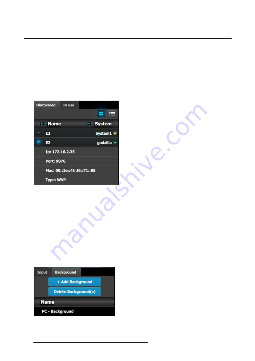
C1: Initial Setup
1. When you connect to an actual unit, instead of working of
fl
ine, the software should connect automatically. The unit is listed in the
System con
fi
guration page under the “Discovered” tab with the button on turning green.
2. Drop the E2 from the device area into the middle diagram area.
3. If multiple units are connected to the PC, the green LEDs next to the system name will turn green. You can assign a unique name
to each unit. In this application we will connect to only one unit and assign the name “Godzilla” to it. For online operations, you
can con
fi
rm that you are connected to the right unit by clicking the arrow in front of E2 to reveal the unit’s IP address. Verify that
this address is the same as the address listed on the unit’s front panel on the top status menu
Image 9-5
Note:
If the unit doesn’t connect automatically to the PC, you can type the PC’s IP address in the
fi
eld under “Manual Connect”.
4. For this application we will leave the default setting for Native rate: 59.94, Mode: 2K and Genlock: OFF.
C2: Add Background
1. Click on the “Background” tab to select the input that will be assigned as a background.
2. Click on the
+Add Background
blue button to enter the Add mode.
3. Click on the top DVI connector of slot 6 to select the input to de
fi
ne as background.
4. Click on the bottom DVI connector of slot 6 to select the input to de
fi
ne as background. We need to do this twice because the
background comes from a dual-head DVI card.
5. Click on the
Done Adding
button to exit the Add mode.
6. Double click on
Background1
in the Name list to edit the name.
7. When the area turns blue, click the eraser icon to clear the
fi
eld.
8. Type a new name, “PC-Background”. Hit enter when done.
Image 9-6
266
R5905948 EVENT MASTER DEVICES 17/07/2017
Содержание S3 series
Страница 1: ...Event Master Devices User s Guide R5905948 05 17 07 2017 ...
Страница 9: ...Table of contents Index 531 R5905948 EVENT MASTER DEVICES 17 07 2017 5 ...
Страница 10: ...Table of contents 6 R5905948 EVENT MASTER DEVICES 17 07 2017 ...
Страница 20: ...2 Safety 16 R5905948 EVENT MASTER DEVICES 17 07 2017 ...
Страница 66: ...4 Hardware orientation 62 R5905948 EVENT MASTER DEVICES 17 07 2017 ...
Страница 90: ...5 Front Panel Menu orientation 86 R5905948 EVENT MASTER DEVICES 17 07 2017 ...
Страница 264: ...8 Updating firmware 260 R5905948 EVENT MASTER DEVICES 17 07 2017 ...
Страница 268: ...9 General operation example Image 9 3 264 R5905948 EVENT MASTER DEVICES 17 07 2017 ...
Страница 285: ...9 General operation example Image 9 25 R5905948 EVENT MASTER DEVICES 17 07 2017 281 ...
Страница 288: ...9 General operation example 284 R5905948 EVENT MASTER DEVICES 17 07 2017 ...
Страница 316: ...10 Controller orientation 312 R5905948 EVENT MASTER DEVICES 17 07 2017 ...
Страница 326: ...11 Controller Configuration 322 R5905948 EVENT MASTER DEVICES 17 07 2017 ...
Страница 352: ...12 Controller Operation 348 R5905948 EVENT MASTER DEVICES 17 07 2017 ...
Страница 356: ...13 E2 Maintenance 13 2 Process Overview Flow chart Image 13 2 352 R5905948 EVENT MASTER DEVICES 17 07 2017 ...
Страница 417: ...13 E2 Maintenance Disregard the heatsink from the spare kit R5905948 EVENT MASTER DEVICES 17 07 2017 413 ...
Страница 418: ...13 E2 Maintenance 414 R5905948 EVENT MASTER DEVICES 17 07 2017 ...
Страница 422: ...14 S3 Maintenance 14 2 Process Overview Flow chart Image 14 2 418 R5905948 EVENT MASTER DEVICES 17 07 2017 ...
Страница 488: ...16 EC 200 Maintenance 484 R5905948 EVENT MASTER DEVICES 17 07 2017 ...
Страница 494: ...17 Environmental information 490 R5905948 EVENT MASTER DEVICES 17 07 2017 ...
Страница 512: ...A Specifications 508 R5905948 EVENT MASTER DEVICES 17 07 2017 ...
Страница 527: ...C Troubleshooting C TROUBLESHOOTING R5905948 EVENT MASTER DEVICES 17 07 2017 523 ...
Страница 528: ...C Troubleshooting 524 R5905948 EVENT MASTER DEVICES 17 07 2017 ...


