6. EM GUI orientation
6.20 Programming Menu > Diagram area
General
The middle of the Programming Page is the Programming diagram area where the
Program
,
Preview
and
AUX
screens are com-
posed.
Description
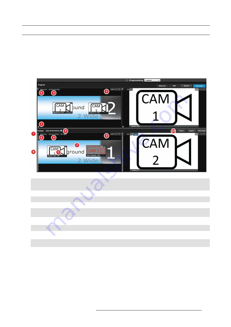
Each Program/Preview screen can be viewed individually or all of the screens can be shown simultaneously by selecting the corre-
sponding tab on the top of the Program window.
On the top left corner has a label that shows the name of the destination.
Image 6-43
1
Lock icon indicates whether the PGM destination is locked. When locked, the Program screen can only change after a
Mix or Cut transition. When the program screen is unlocked, the user can click on a layer that is on PGM and move or
resize it. The user can also assign a different Source into that layer or adjust the background.
2
Preview screen where the program is composed before is transitioned to program.
3
Users can zoom in / out of the diagram area, in from 25% to 150%, in 25% increments.
4
BG Input tab. This is the menu where users drop the assigned Background inputs preview screens.
5
Selected sources are dropped in the layers de
fi
ned in the preview screen. A layer can be placed outside or partially in
the preview area.
6
The Destination tab can be clicked to arm the Destination and become part of the next transition.
7
A small arrow on the left hand side of Destination name expands or collapses the Destination view.
8
Users can manually control the transition by clicking on the bar or by sliding the mouse.
9
Select all Destinations allow to quickly select or unselect all Destinations for Transition.
10
Layouts allow for custom layouts of destinations in the programming page.
Layer and Source into the previous screen
Users can drag layers to the preview screen as long as the layer is not on program. In the example below, since no source has been
assigned to the layer, the layer will be black and default to a square shape.
R5905948 EVENT MASTER DEVICES 17/07/2017
163
Содержание S3 series
Страница 1: ...Event Master Devices User s Guide R5905948 05 17 07 2017 ...
Страница 9: ...Table of contents Index 531 R5905948 EVENT MASTER DEVICES 17 07 2017 5 ...
Страница 10: ...Table of contents 6 R5905948 EVENT MASTER DEVICES 17 07 2017 ...
Страница 20: ...2 Safety 16 R5905948 EVENT MASTER DEVICES 17 07 2017 ...
Страница 66: ...4 Hardware orientation 62 R5905948 EVENT MASTER DEVICES 17 07 2017 ...
Страница 90: ...5 Front Panel Menu orientation 86 R5905948 EVENT MASTER DEVICES 17 07 2017 ...
Страница 264: ...8 Updating firmware 260 R5905948 EVENT MASTER DEVICES 17 07 2017 ...
Страница 268: ...9 General operation example Image 9 3 264 R5905948 EVENT MASTER DEVICES 17 07 2017 ...
Страница 285: ...9 General operation example Image 9 25 R5905948 EVENT MASTER DEVICES 17 07 2017 281 ...
Страница 288: ...9 General operation example 284 R5905948 EVENT MASTER DEVICES 17 07 2017 ...
Страница 316: ...10 Controller orientation 312 R5905948 EVENT MASTER DEVICES 17 07 2017 ...
Страница 326: ...11 Controller Configuration 322 R5905948 EVENT MASTER DEVICES 17 07 2017 ...
Страница 352: ...12 Controller Operation 348 R5905948 EVENT MASTER DEVICES 17 07 2017 ...
Страница 356: ...13 E2 Maintenance 13 2 Process Overview Flow chart Image 13 2 352 R5905948 EVENT MASTER DEVICES 17 07 2017 ...
Страница 417: ...13 E2 Maintenance Disregard the heatsink from the spare kit R5905948 EVENT MASTER DEVICES 17 07 2017 413 ...
Страница 418: ...13 E2 Maintenance 414 R5905948 EVENT MASTER DEVICES 17 07 2017 ...
Страница 422: ...14 S3 Maintenance 14 2 Process Overview Flow chart Image 14 2 418 R5905948 EVENT MASTER DEVICES 17 07 2017 ...
Страница 488: ...16 EC 200 Maintenance 484 R5905948 EVENT MASTER DEVICES 17 07 2017 ...
Страница 494: ...17 Environmental information 490 R5905948 EVENT MASTER DEVICES 17 07 2017 ...
Страница 512: ...A Specifications 508 R5905948 EVENT MASTER DEVICES 17 07 2017 ...
Страница 527: ...C Troubleshooting C TROUBLESHOOTING R5905948 EVENT MASTER DEVICES 17 07 2017 523 ...
Страница 528: ...C Troubleshooting 524 R5905948 EVENT MASTER DEVICES 17 07 2017 ...


