background image

R5906167 /00

ImagePRO

4K Video Processor

97

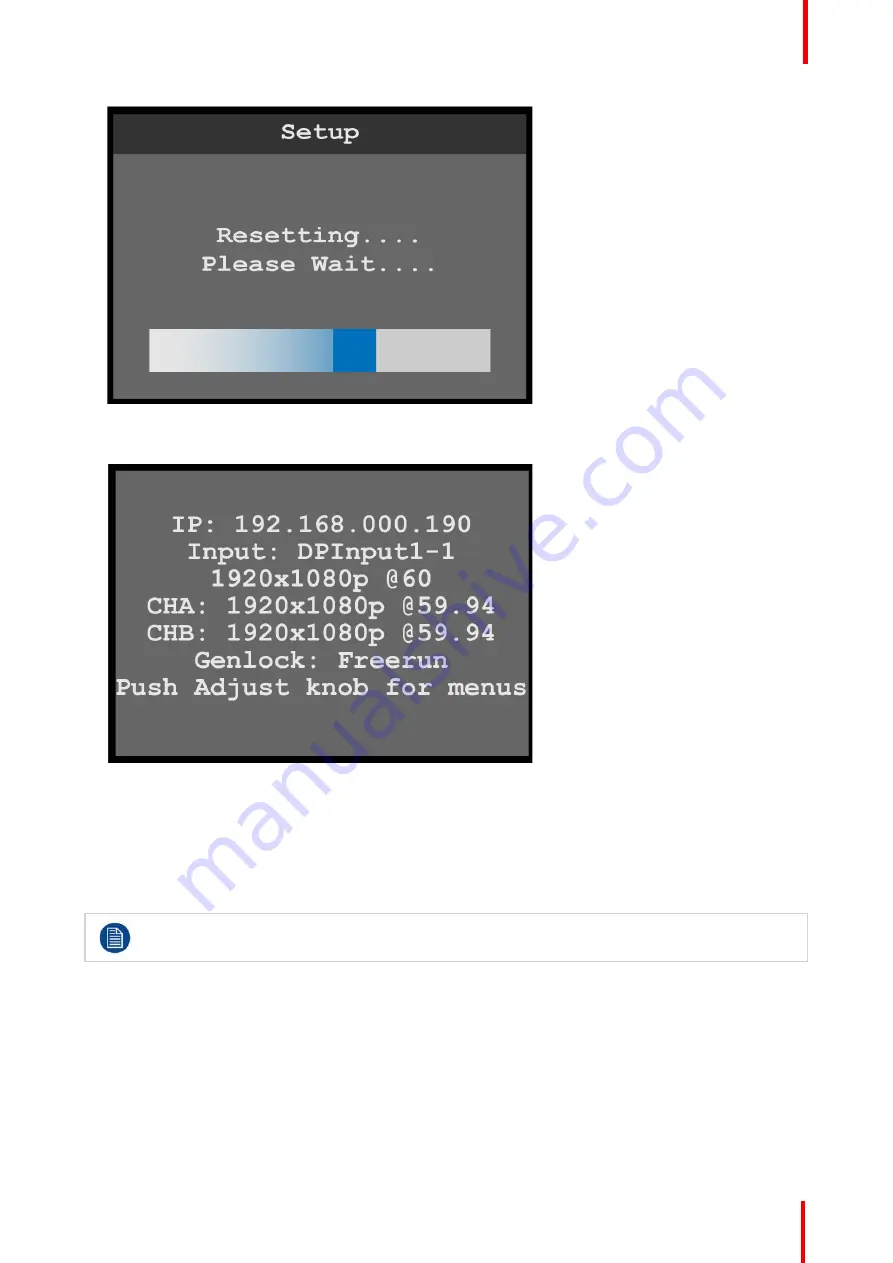
Image 6-118: Reset progress bar

When the system has been reset, the system displays a status screen.

Image 6-119: Status after reset

6.11 Firmware upgrade menu

General

This section provides information about the Firmware upgrade menu.

Refer to

Upgrading firmware

page 111 for instructions on performing a firmware upgrade.

To enter the Firmware upgrade menu from the Setup menu, scroll to and select

Firmware upgrade

.

Firmware upgrade menu tree

Refer to Image 6-120 for an illustration of the Firmware upgrade menu tree.

Menu orientation

Содержание ImagePRO

Страница 1: ...ENABLING BRIGHT OUTCOMES User s Guide ImagePRO 4K Video Processor...

Страница 2: ...ss Barco NV President Kennedypark 35 8500 Kortrijk Belgium www barco com en support www barco com Barco Inc Image Processing 3078 Prospect Park Drive Rancho Cordova CA 95670 USA www barco com en suppo...

Страница 3: ...o being a component of the system or independent service will be deemed invalid provided the damage is not proven to be attributed to the absence of properties guaranteed in writing or due to the inte...

Страница 4: ...e responsible for correcting any interference at his own expense Changes or modifications not expressly approved by the party responsible for compliance could void the user s authority to operate the...

Страница 5: ...5 Overview About this guide Record of changes Symbols pictures and fonts R5906167 00 ImagePRO 4K Video Processor Introduction 1...

Страница 6: ...Available system documentation This guide is part of the documentation set describing the ImagePRO 4K product Guide Article number Quick Start Guide 26 1602004 00 User Guide R5906167 Service Guide R59...

Страница 7: ...xtra advice about the described subject Picture overview Images and pictures given in the manual are used as illustration The content of the images can be slightly different from the reality e g versi...

Страница 8: ...R5906167 00 ImagePRO 4K Video Processor 8 Introduction...

Страница 9: ...the device Ensure that you understand and follow all safety guidelines safety instructions and warnings mentioned in this chapter before you begin installation After this chapter additional warnings a...

Страница 10: ...against the risk of fire Simulated single fault condition testing ensures the safety of the equipment to the user even when the equipment s normal operation fails 2 2 Certificates CE mark Image 2 1 CE...

Страница 11: ...and ground A protective ground connection by way of grounding conductor in the power cord is essential for safe operation This product is grounded through the grounding conductor of the power cord To...

Страница 12: ...R5906167 00 ImagePRO 4K Video Processor 12 Safety...

Страница 13: ...troduce you to the ImagePRO 4K video processor Overview ImagePRO 4K video processor overview ImagePRO 4K video processor features Terms and definitions Unpacking and inspection Installation requiremen...

Страница 14: ...hrough the process External control You can remotely control all ImagePRO 4K features from a computer using the Event Master Toolset EMTS GUI With the easy to use pages menus and graphics of the EMTS...

Страница 15: ...e is primarily used to connect a video source to a display device such as a computer monitor though it can also be used to transmit audio USB and other forms of data VESA designed it to replace VGA DV...

Страница 16: ...luma R Y 3 4 Unpacking and inspection General Before shipment all the devices were inspected and found to be free of mechanical and electrical defects As soon as the devices are unpacked inspect for...

Страница 17: ...measures to prevent the dust from reaching the unit If this is not a feasible then the unit should be relocated to a different dust free location It is the customer s responsibility to ensure at all t...

Страница 18: ...hassis These side rails when they are properly installed and adjusted assist with the distribution of chassis and cable weight within your rack Use the following steps to properly adjust the side rail...

Страница 19: ...RO 4K performs line voltage selection automatically No user controls are required The AC power cords must be accessible so that they can be removed during field servicing WARNING When used above 230 v...

Страница 20: ...R5906167 00 ImagePRO 4K Video Processor 20 General...

Страница 21: ...21 About this chapter This chapter explains the ImagePRO 4K video processor s hardware in detail Overview Front panel Rear panel R5906167 00 ImagePRO 4K Video Processor Hardware Orientation 4...

Страница 22: ...to select menu items 4 Menu Monitor mode toggle button The Menu Monitor mode toggle button toggles the display between Menu mode and Monitor mode 5 LED setup button The LED setup button accesses the...

Страница 23: ...ables Neutrik EtherCon series cables 3 BNC Genlock In Genlock analog reference input is through a BNC connector with fixed 75 ohm termination and supports Blackburst and Bi level at SD and supports Tr...

Страница 24: ...ock at 24 bits pixel 620 Mpix sec Max pixel clock at 30 bits pixel 576 Mpix sec Max pixel clock at 36 bits pixel 480 Mpix sec Supported formats Formats up to 4096x2160 60 30 bits 4K UHD supported 3840...

Страница 25: ...59 94 60 60 as 4x 3G SDI Level A and B supported Genlock input connector The genlock input supports NTSC and PAL Blackburst as well as SD bi level and HD tri level sync signals per SMPTE 274M and SMP...

Страница 26: ...R5906167 00 ImagePRO 4K Video Processor 26 Hardware Orientation...

Страница 27: ...operating your system follow the steps in this section Links are provided to the appropriate sections in this guide if you require more information Overview Rear panel connections Front panel operatio...

Страница 28: ...on power Turn on power to the ImagePRO 4K your connected display devices and to all peripheral equipment 5 2 Front panel operation Front panel features Refer to Front panel page 22 for the location a...

Страница 29: ...2 Turn the Adjust knob to scroll up or down through the menus Turn the knob clockwise to scroll down Turn the knob counter clockwise to scroll up 3 Press the Adjust knob to select menu items MENU MON...

Страница 30: ...nu key to enter the Test Pattern menu 2 Scroll through the Test Pattern menu to select the Aux channel and the type of test pattern and to set the AOI Raster Box the Output Raster Box and the Diagonal...

Страница 31: ...efault system configurations Press the Adjust knob to enter the Setup menu then select Reset Factory on the display screen Reset Soft Reset keeps the user settings 2 Native Rate On the front panel pre...

Страница 32: ...source 9 Adjust and save system settings Adjust system parameters such as Ethernet settings and HDCP parameters 10 Save All Select Save All Save All is the last menu item on the Setup page Save All wr...

Страница 33: ...The principal menu trees are presented in block diagram format throughout the chapter Overview Power up initialization ImagePRO 4K menus Input menu Output Aux menu Still menu Preset menu Button Mappin...

Страница 34: ...ing the front panel buttons light up and the Barco logo and the following messages are displayed Image 6 1 Barco logo screen Image 6 2 System initialization In Progress The In Progress message shows t...

Страница 35: ...nels A and B and the Genlock status The status screen also displays a message telling the user to push the Adjust knob to access the menus 6 2 ImagePRO 4K menus ImagePRO 4K menu tree The diagram on th...

Страница 36: ...R5906167 00 ImagePRO 4K Video Processor 36 Image 6 4 Menu tree Menu orientation...

Страница 37: ...puts To enter the Input menu from the Setup menu scroll to and select Input Image 6 6 Setup menu Input Use the Input Menu to adjust all parameters relating to inputs Using this menu you can set all of...

Страница 38: ...R5906167 00 ImagePRO 4K Video Processor 38 Image 6 7 Input menu tree Menu orientation...

Страница 39: ...on the Input menu Once Input is selected the highlight bar turns from gray to cyan Turning the adjust knob scrolls through the available inputs 2 Scroll to and select the input to be configured Image...

Страница 40: ...mat Adjustment to view or adjust the Color Space Color Range Bit Depth and Detailed Timing The options for these adjustments are Color Space RGB SMPTE Color Range Full Range Reduced Range Bit Depth 8...

Страница 41: ...The default HDCP mode setting for DisplayPort DVI and HDMI is Off HDCP Mode is not applicable to SDI inputs 7 Scroll to and select Save Input to save the selected input settings Source The Input Sourc...

Страница 42: ...le the Mode is 3 1 the Ratio is 3 00 Turning the adjust knob counter clockwise users can adjust the ratio to any custom setting for example from 2 99 to 1 78 Setting the Ratio to 1 77 sets the Mode to...

Страница 43: ...settings 5 Scroll to and select Save Source to save any adjusted source settings a Overwrite Source overwrites the current source configuration with the adjusted settings b Save As saves the adjusted...

Страница 44: ...s information about setting up and using outputs Auxes To enter the Output Aux menu from the Setup menu scroll to and select Output Aux Image 6 17 Setup menu Output Aux Use the Output Aux Menu to adju...

Страница 45: ...R5906167 00 ImagePRO 4K Video Processor 45 Image 6 18 Output Aux menu tree Menu orientation...

Страница 46: ...R5906167 00 ImagePRO 4K Video Processor 46 Image 6 19 Output Aux menu tree Continued Select Aux 1 Select Select Aux on the Output Aux menu Menu orientation...

Страница 47: ...Image 6 21 Output Aux channel selection Aux Adjustment 1 Scroll to and select Aux Adjustment The Aux Adjustment menu allows users to manually format the resolution and refresh rate to auto configure...

Страница 48: ...V Size adjusts the vertical size of the AOI H Pos adjusts the horizontal position of the AOI V Pos adjusts the vertical position of the AOI Reset returns all adjustments to their initial settings 6 S...

Страница 49: ...to and select Mask to view or adjust masking options Scaling Mode can be set to All Center Cut or Custom For custom configurations other adjustments can be made Custom Mask values are given in percen...

Страница 50: ...ust knob to scroll through the possible color space sampling rate and bit depth settings for the selected output 4 Press the adjust knob to select the desired color space sampling rate and bit depth s...

Страница 51: ...cyan Image 6 26 Output Aux Primary Output 2 Turn the adjust knob to scroll through the outputs 3 Press the adjust knob to select the desired output SDI Setup 1 Scroll to and select SDI Setup on the Ou...

Страница 52: ...o select the desired level 5 Scroll to and select Make Quad SDI Output Image 6 28 SDI Setup quad SDI output 6 If necessary scroll to and select the quad SDI output Once the output is selected the high...

Страница 53: ...enu Still Still menu tree Refer to Image 6 30 for an illustration of the Still menu tree Image 6 30 Still menu tree Capture New Still 1 Select Capture New Still on the Still menu Image 6 31 Setup menu...

Страница 54: ...nce the still has been captured the system displays a message that includes the name of the still Image 6 33 New Still captured Select Still 1 Select Select Still on the Still menu Once the Select Sti...

Страница 55: ...ed as Logo 1 Select the still to be used as a logo 2 Select Set Selected as Logo on the Still menu The system displays a message that says that the selected still has been set as a logo Image 6 35 Sti...

Страница 56: ...has been removed Image 6 37 Still menu Still removed 6 6 Preset menu General This section provides information about setting up and using presets A preset is a register that enables you to store dest...

Страница 57: ...e 6 39 for an illustration of the Preset menu tree Image 6 39 Preset menu tree Save New Preset 1 Select Save New Preset on the Preset menu Once Input is selected the highlight bar turns from gray to c...

Страница 58: ...Select Preset 2 Use the adjust knob to scroll to and select the desired preset 3 Select Recall Preset to recall the newly selected preset Overwrite Preset 1 Select Overwrite Preset on the Preset menu...

Страница 59: ...nt to delete the preset Image 6 43 Preset menu Delete message 2 Select Yes to delete the selected preset Select No to keep the preset Once the preset has been deleted the system displays a message tha...

Страница 60: ...information about mapping the front panel buttons To enter the Button Mapping menu from the Setup menu scroll to and select Button Mapping Image 6 46 Setup menu Button Mapping Use the Button Mapping m...

Страница 61: ...Buttons on the Button Mapping menu Image 6 48 Button Mapping menu Source Buttons 2 Scroll to and select the input to be configured Once the input to be configured is selected the highlight bar turns f...

Страница 62: ...2 and 3 for each button that is to be mapped The default mapping for Button 7 is Matte and the default mapping for Button 8 is Logo 5 To unmap all of the source buttons scroll to and select Unmap All...

Страница 63: ...ntly mapped source buttons and automatically remaps them When the remapping is finished the system displays a message Image 6 52 All source buttons mapped message 7 Select Yes to complete the auto map...

Страница 64: ...turns from gray to cyan Turning the adjust knob scrolls through the channels available to that button Image 6 54 Output Buttons menu 3 Scroll to and select the channel A or B to be configured You may...

Страница 65: ...ed output buttons and automatically remaps them When the remapping is finished the system displays a message Image 6 56 All output buttons mapped message 6 Select Yes to complete the auto mapping of t...

Страница 66: ...he front panel buttons to all available sources and outputs 1 Select Auto Map All Buttons on the Button Mapping menu Image 6 58 Auto Map All Buttons The system unmaps all currently mapped source and o...

Страница 67: ...l source and output buttons Source button states Brightly lit Button is selected Green Signal is active and assigned to PVW Yellow Input source still logo or matte color is present Amber Source is act...

Страница 68: ...on the front panel are unlit Image 6 62 Front panel source and output buttons unmapped 6 8 System menu General This section provides information about the System menu To enter the System menu from th...

Страница 69: ...e operator can preview the input on the Display screen before taking it to program by pressing the Take button Note that to preview the selected input on the display screen the MENU MON menu key must...

Страница 70: ...st be defined by the user Each output can have a different signal rate from the others as well as a unique area of interest To select the unit mode 1 Select Unit Mode on the System menu Once Unit Mode...

Страница 71: ...eo is selected the highlight bar turns from gray to cyan Image 6 68 System menu Native Rate 2 Scroll through and select from among the native rate options The native rate of the system is measured in...

Страница 72: ...l if present 2 Scroll to and select the desired Genlock parameter Once a parameter is selected the highlight bar for that parameter turns from gray to cyan 3 Scroll through and select the options for...

Страница 73: ...if a FAT32 formatted USB drive is in the front panel USB port If the system detects no USB drive in the USB port the top line of the USB Backup Restore menu reads USB Detected No If the system detects...

Страница 74: ...has an EM folder the system creates a backup file for example USBBackup1 tar gz and places it in a folder named EM backup sys If the USB drive does not have an EM folder the system creates a folder n...

Страница 75: ...ackup is In Progress and Do NOT power cycle Image 6 75 Backup In Progress message When the restore operation is finished the system then displays a message that asks Restart Unit Now Image 6 76 Restor...

Страница 76: ...parameters of the system 1 Select Ethernet on the System menu 2 Scroll to and select the desired Ethernet parameter for example DHCP Dynamic Host Configuration Protocol Once Ethernet parameter is sele...

Страница 77: ...reached 3 Repeat Step 2 for each portion of the IP address 4 Select Set Subnet Mask from the Set Static IP menu 5 Use the adjust knob to adjust the first portion of the Subnet Mask and press the adju...

Страница 78: ...of the front panel buttons Image 6 81 System menu Button Brightness Once Button Brightness is selected the highlight bar turns from gray to cyan 2 Scroll through the button brightness settings from 0...

Страница 79: ...the highlight bar turns from gray to cyan 2 Scroll between Off default and On and select the desired setting When Flash Display is set to On the display flashes from dark to dim to bright Diagnostics...

Страница 80: ...y be disrupted Front panel diagnostics 1 Scroll to and select Front Panel from the Diagnostics menu Image 6 86 Diagnostics menu Front Panel When Front Panel is selected the system displays the message...

Страница 81: ...adjust knob or press any front panel button for example the ESC button Image 6 88 Exit front panel diagnostics 3 Press and hold the ESC button to return to the Diagnostics menu Buttons Encoder diagno...

Страница 82: ...ns Encoder When Buttons Encoder is selected the system displays the message Diagnostics in progress Please press the button or turn the knob Image 6 90 Diagnostics in Progress 2 Turn the adjust knob o...

Страница 83: ...he ESC button to return to the Diagnostics menu Card diagnostics 1 Scroll to and select Card Diagnostics from the Diagnostics menu Image 6 92 Diagnostics menu Card Diagnostics 2 Select Slot from the C...

Страница 84: ...nd 3 4 Scroll to and select Perform Test The system displays the following warning message Image 6 94 Card Diagnostics Slot warning message 5 Select Yes to perform the card diagnostics If No is select...

Страница 85: ...finished the system displays the results Image 6 96 Board diagnostics results 6 Press the ESC key to return to the Card Diagnostics menu Temperature diagnostics 1 Scroll to and select Temperature fro...

Страница 86: ...flash drive in the front panel USB slot If there is no USB drive in the USB slot when you attempt to create backup log files the system displays the message USB drive not found Please check USB conne...

Страница 87: ...of the backup file Image 6 100 Backup successful message The system stores the backup file IP4KLogFiles tar gz in the EM folder on the USB drive 6 9 Custom Formats General This section provides infor...

Страница 88: ...ation of the initial Custom Formats menu tree This reflects how the Custom Formats menu appears on the display screen before any custom formats are created Image 6 102 Custom Formats menu tree with no...

Страница 89: ...ng an existing format users should be familiar with how the adjustments they are making may affect the video format The user should use a timing calculator to determine the correct numbers for timing...

Страница 90: ...active area and the beginning of H sync H Active The horizontal size in pixels of the active area H Sync H sync width in pixels V Total Total line count per frame V FrontPorch The offset in lines bet...

Страница 91: ...Scroll through and select the desired custom format for example CustomFormat 4 Delete 1 Scroll to and select Delete to delete the selected format Image 6 107 Custom Formats menu Delete The system dis...

Страница 92: ...A if no custom formats are available Image 6 109 Custom Formats menu Deleted format Selected Base Format Any custom format can serve as a base format for another custom format Once a selected base for...

Страница 93: ...Image 6 111 Custom Formats menu H Active 2 Turn the adjust knob clockwise to increase or counter clockwise to decrease the value of the selected property Save As If after adjusting the properties of...

Страница 94: ...up to 21 characters 4 Press the adjust knob once you have entered the new name for the custom format The system displays a message that says that the custom format has been saved Image 6 113 Custom Fo...

Страница 95: ...enter the Reset menu from the System menu scroll to and select Reset Image 6 114 Setup menu Reset Use the Reset menu to perform a factory reset Reset menu tree Refer to Image 6 115 for an illustratio...

Страница 96: ...ions except that it saves the current IP address Factory Save IP EDID restores all default system configurations except that it saves the current IP address and EDID settings Soft keeps the user setti...

Страница 97: ...upgrade menu General This section provides information about the Firmware upgrade menu Refer to Upgrading firmware page 111 for instructions on performing a firmware upgrade To enter the Firmware upgr...

Страница 98: ...enu scroll to and select Tech Support Image 6 121 Setup menu Tech Support Use the Custom Formats menu to create custom formats to match different output devices Tech Support 1 Scroll to and select Tec...

Страница 99: ...e operator to save all system settings To enter the Save All menu from the Setup menu scroll to and select Save All Image 6 123 Setup menu Save All Use the Save All menu to save all of the system sett...

Страница 100: ...R5906167 00 ImagePRO 4K Video Processor 100 Image 6 124 Saved settings message 2 Click on OK The system saves the settings file and returns to the Setup menu Menu orientation...

Страница 101: ...nu EMTS GUI Programming menu ImagePRO 4K specific controls General In the EMTS GUI add the detected ImagePRO 4K processor as a new system and click the ImagePRO 4K banner at the bottom of the represen...

Страница 102: ...tle bar shows the current menu and the currently selected system 3 Selection area The selection area contains tabs for Discovered systems and systems In use It also contains a field for entering IP ad...

Страница 103: ...tabs The Settings and Setup subtabs allow users to adjust system settings The Status subtab displays the status of the selected item unit input output etc These subtabs differ depending on the item se...

Страница 104: ...d Program ChannelA Program ChannelA shows the signal that is active on ChannelA on Program PRG to output 3 Workspace System wide function area This area contains Layer alignment adjustments and contro...

Страница 105: ...7 00 ImagePRO 4K Video Processor 105 Image 7 4 ImagePRO 4K specific configuration controls 1 Configuration menu 2 Graphic representation of the ImagePRO 4K unit 3 Adjust tab 4 Setup tab Event Master T...

Страница 106: ...he current matte color Select a standard color from among the boxes above the color wheel Use the color wheel Select a color on the color wheel Click the Learn button below the color wheel Assign the...

Страница 107: ...ode the system automatically places the Logo in ChannelA Program In Standard Preview mode the operator must use either the All Trans key or the Cut key to place the Logo in ChannelA Program The IP4K t...

Страница 108: ...R5906167 00 ImagePRO 4K Video Processor 108 Event Master Toolset...

Страница 109: ...109 About this annex This annex gives an overview of the specifications of the ImagePRO 4K video processor R5906167 00 ImagePRO 4K Video Processor Specifications A...

Страница 110: ...le scaler outputs supporting independent scaling sizing and color correction Mixers N A Still stores Up to 100 HD or 25 UHD Import file is size dependent Layer effects N A Multiviewer Video preview on...

Страница 111: ...111 About this annex This annex provides information regarding the upgrading of firmware on the ImagePRO 4K R5906167 00 ImagePRO 4K Video Processor Upgrading firmware B...

Страница 112: ...the flash drive erases existing data To avoid losing data download to a computer or a secure site any files you wish to keep then format the drive How to format the flash drive 1 Insert the flash driv...

Страница 113: ...the created login and password it is possible to login where you can download the Event Master series processor software It is not necessary to install any other software 2 Unzip directly the software...

Страница 114: ...e Upgrade USB Upgrade 5 Select the upgrade file Image B 4 USB Upgrade Select File 6 Scroll to and select Update The system displays an In Progress screen and a warning to NOT power cycle the unit Imag...

Страница 115: ...splays a progress bar and then the In Progress screen When the firmware upgrade is finished the system displays a post upgrade status screen Image B 7 Post upgrade status screen CAUTION Do not remove...

Страница 116: ...R5906167 00 ImagePRO 4K Video Processor 116 Upgrading firmware...

Страница 117: ...117 Overview Disposal information RoHS compliance Contact information R5906167 00 ImagePRO 4K Video Processor Environmental information C...

Страница 118: ...red by the Directive 2006 66 EC which must be collected and disposed of separately from municipal waste If the battery contains more than the specified values of lead Pb mercury Hg or cadmium Cd these...

Страница 119: ...ectronic Information Products EIP that are sold within Chinese Mainland must comply with the Marking for the restriction of the use of hazardous substances in electrical and electronic product of Chin...

Страница 120: ...4K Video Processor 120 Factories Barco Inc 3000 Technology Road Angleton TX 77515 USA Production date The month and year of production is indicated on the product ID label on the product itself Envir...

Страница 121: ...software components are reusable software components developed to be either freely distributed or sold by an entity other than the original vendor of the development platform Overview Third Party Sof...

Страница 122: ...urce and binary form without fee Xorg is copyright by numerous authors and contributors from around the world Licensing information can be found at http www x org Refer to the source code for specific...

Страница 123: ...123 About this annex This chapter gives an overview of Warranty and conditions of RMA concerning the Event Master devices R5906167 00 ImagePRO 4K Video Processor Warranty E...

Страница 124: ...ults resulting from user negligence special modifications lightning strikes abuse drop crush and or other unusual damages The customer shall pay shipping charges when unit is returned for repair Barco...

Страница 125: ...R5906167 00 ImagePRO 4K Video Processor 125 Warranty...

Страница 126: ...Barco Inc Image Processing 3078 Prospect Park Drive Rancho Cordova CA 95670 USA Registered address Barco NV President Kennedypark 35 8500 Kortrijk Belgium www barco com R5906167 00 2018 11 30...

Отзывы: