10. Card Cage
10.2 Removal of the Input & Communication Unit
W
ARNING
:
The procedures below may only be performed by Barco trained and quali
fi
ed technicians.
C
AUTION
:
The connector seats are fragile. Make sure to push the little tab when pulling the connector out or
the connector can get damaged.
Necessary tools
7 mm
fl
at screwdriver
How to remove the Input & Communication Unit?
1. Switch off the projector and unplug the power cord at the projector back side.
2. Ensure that no cables are connected to one of the ports of the Input & Communication Unit.
3. Remove the left projector cover.
4. Release the 4 captive screws in the corners of the Input & Communication Unit.
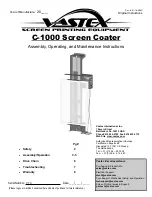
5. Pull the Input & Communication Unit partly out of its compartment until the hinge cylinder (reference 1) is at the right place.
6. Tip over the Input & Communication Unit.
7. Disconnect the wires:
a) Disconnect the left connector (reference 2) by pulling it out of its socket.
b) Disconnect the RGB connectors (reference 3) by pushing the little tab (reference 4) and pulling the connectors out of their
sockets.
Caution:
The connector seats are fragile. Make sure to push the little tab when pulling the connector out or the connector can
get damaged.
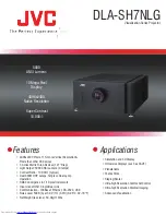
8. Bring the Input & Communication Unit back to a vertical position and slide it fully out of its compartment.
144
R5905312 HDF W SERIES 24/01/2013
Содержание HDF W series
Страница 1: ...HDF W series Service manual R5905312 01 24 01 2013 ...
Страница 4: ......
Страница 8: ...Table of contents 4 R5905312 HDF W SERIES 24 01 2013 ...
Страница 12: ...1 Safety 8 R5905312 HDF W SERIES 24 01 2013 ...
Страница 30: ...3 Preventative maintenance actions 26 R5905312 HDF W SERIES 24 01 2013 ...
Страница 35: ...5 Troubleshooting 5 TROUBLESHOOTING R5905312 HDF W SERIES 24 01 2013 31 ...
Страница 36: ...5 Troubleshooting 32 R5905312 HDF W SERIES 24 01 2013 ...
Страница 110: ...6 Removal and installation of the projector covers 106 R5905312 HDF W SERIES 24 01 2013 ...
Страница 111: ...7 Power Input 7 POWER INPUT R5905312 HDF W SERIES 24 01 2013 107 ...
Страница 112: ...7 Power Input 108 R5905312 HDF W SERIES 24 01 2013 ...
Страница 120: ...7 Power Input 116 R5905312 HDF W SERIES 24 01 2013 ...
Страница 172: ...10 Card Cage 168 R5905312 HDF W SERIES 24 01 2013 ...
Страница 182: ...11 Lamp Power Supply 178 R5905312 HDF W SERIES 24 01 2013 ...
Страница 183: ...12 Start Pulse Generator 12 START PULSE GENERATOR R5905312 HDF W SERIES 24 01 2013 179 ...
Страница 184: ...12 Start Pulse Generator 180 R5905312 HDF W SERIES 24 01 2013 ...
Страница 192: ...12 Start Pulse Generator 188 R5905312 HDF W SERIES 24 01 2013 ...
Страница 242: ...14 Lenses and Lens Holder 238 R5905312 HDF W SERIES 24 01 2013 ...
Страница 266: ...15 Liquid cooling circuit Image 15 39 Electrical connection 262 R5905312 HDF W SERIES 24 01 2013 ...
Страница 269: ...15 Liquid cooling circuit Image 15 45 Electrical connection R5905312 HDF W SERIES 24 01 2013 265 ...
Страница 270: ...15 Liquid cooling circuit 266 R5905312 HDF W SERIES 24 01 2013 ...
Страница 274: ...16 Heat exchanger Image 16 5 Remove assembly 270 R5905312 HDF W SERIES 24 01 2013 ...
Страница 280: ...16 Heat exchanger Image 16 13 276 R5905312 HDF W SERIES 24 01 2013 ...
Страница 309: ...19 Board Diagnostic LED s 19 BOARD DIAGNOSTIC LED S R5905312 HDF W SERIES 24 01 2013 305 ...
Страница 310: ...19 Board Diagnostic LED s 306 R5905312 HDF W SERIES 24 01 2013 ...
Страница 328: ...19 Board Diagnostic LED s 324 R5905312 HDF W SERIES 24 01 2013 ...