


FSN Series • User’s Guide
209
5. Menu Orientation
System Menu
bñíÉêå~ä=aph=q~ÄäÉ
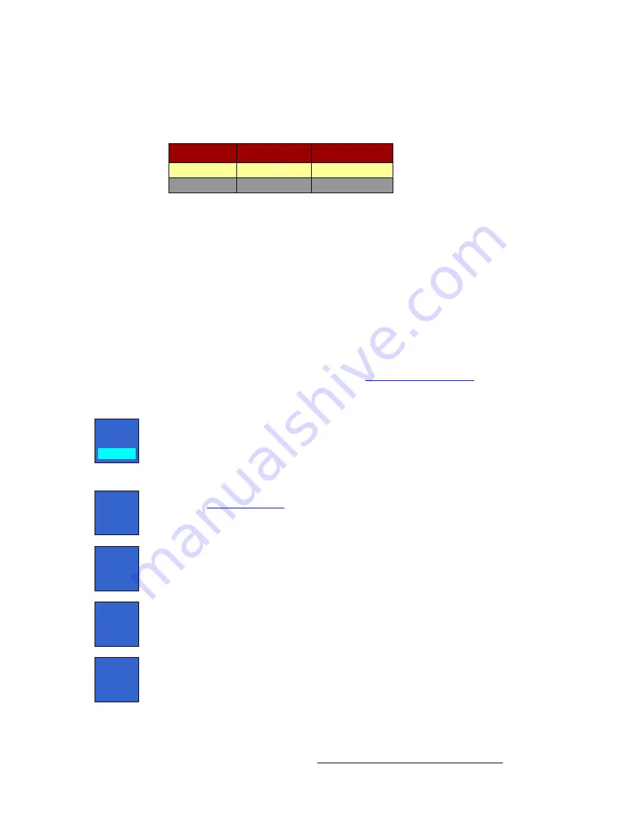
The
External DSK Table
provides information about each input. The yellow highlight
automatically tracks the selected input connector in the
Rear I/O View
.
Figure 5-98.
External DSK Table (sample)
The following columns of information are provided:
•
Name
— indicates the name of the selected connector (
DSK Cut
or
DSK Fill
).
•
Format
— displays the input’s format.
•
Error Reporting
— “
On
” indicates that the connector is enabled and error
reporting is active. “
Off
” indicates that error reporting is prevented. Use the
{Error Reporting}
toggle button to toggle the function.
aph=cáää=pÉíìé
To set up the
DSK Fill
input, touch its connector in the
Rear I/O View
. The menu changes
to display the input’s setup functions. In the
Color Correction
section, all functions are
identical to those for native inputs. Refer to the “
” heading on
page 195 for details.
In the
Tool Bar
, the following adjustments are provided:
•
Toggle the
{Error Reporting}
button to either
On
or
Off
:
~
When on, the label “
On
” appears in the table in the
Error Reporting
column, and error reporting is active.
~
When off, the label “
Off
” appears in the table, and error reporting is
prevented.
•
Press
{Info}
to display the
Input Color Legend Pop-up
. Refer to the
“
” section on page 189 for details.
•
Press
{Save Settings}
to save the selected input’s setup parameters in non-
volatile memory.
•
Press
{Restore Saved Settings}
to recall the selected input’s setup parameters
from non-volatile memory.
•
Press
{Restore Default Settings}
to recall the selected input’s default setup
parameters.
Name
EXT DSK Cut
Format
Native
EXT DSK Fill
Native
Error Reporting
On
On
Error
Reporting
On
Info
Save
Settings
Restore
Saved
Settings
Restore
Default
Settings


