9. Image menu
The projected image should now be noisy full black
If one uses a gray scale pattern, the bright spots should appear in the black bar.
Performing White input balance
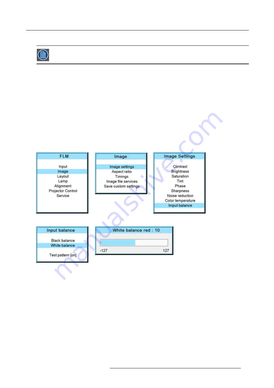
1. Connect the source you want to project.
2. Press
MENU
to activate the menus.
3. Use the
▲
or
▼
key to select
Image
and press
ENTER
.
4. Use the
▲
or
▼
key to select
Image settings
and press
ENTER
.
5. Use the
▲
or
▼
key to select
Input balance
and press
ENTER
.
6. Do you want to use an internally generated test pattern?
If yes, Use the
▲
or
▼
key to select
Test pattern
and press
ENTER
to toggle between [on] and [off]
If no, select a white pattern (or gray scale as alternative).
7. Use the
▲
or
▼
key to select
White balance
and press
ENTER
.
The white balance bar scale for a typical color is displayed.
8. Toggle with the
▲
or
▼
key to select
White balance red
.
Image 9-51
Image 9-52
Image 9-53
Image 9-54
Image 9-55
9. Adjust the red white level (gain) on a minimal value
10.Toggle with
▲
or
▼
key to
White balance blue
and adjust the blue white level (gain) on a minimal value.
Note:
This minimal value is not necessary , provided that the 2 other colors are not in
fl
uencing too much the color to be adjusted,
in fact the aim is to minimize the effect of the two other colors since there is a risk of reaching too soon the transition
(bright spots) due to the contribution of these two other colors signals.
11.Toggle with
▲
or
▼
key to
White balance green
and adjust the Green white level (gain) until bright spots appear on the screen.
12.Toggle with
▲
or
▼
key to
White balance blue
adjust the Blue white level (gain) until bright spots appear on the screen.
13.Toggle with
▲
or
▼
key to
White balance red
adjust the Red white level (gain) until bright spots appear on the screen.
The projected image should now be noisy neutral gray.
R5976921 FLM R20+ PERFORMER 15/03/2010
81
Содержание FLM R20+ Performer
Страница 1: ...FLM R20 Performer Users manual R9004430 R5976921 11 15 03 2010 ...
Страница 34: ...3 Physical installation 30 R5976921 FLM R20 PERFORMER 15 03 2010 ...
Страница 46: ...5 Connections 42 R5976921 FLM R20 PERFORMER 15 03 2010 ...
Страница 62: ...7 Start up of the Adjustment Mode 58 R5976921 FLM R20 PERFORMER 15 03 2010 ...
Страница 72: ...8 Input menu 68 R5976921 FLM R20 PERFORMER 15 03 2010 ...
Страница 98: ...9 Image menu 94 R5976921 FLM R20 PERFORMER 15 03 2010 ...
Страница 114: ...10 Layout menu Image 10 65 Image 10 66 Image 10 67 110 R5976921 FLM R20 PERFORMER 15 03 2010 ...
Страница 120: ...11 Lamp menu 116 R5976921 FLM R20 PERFORMER 15 03 2010 ...
Страница 148: ...12 Alignment menu 144 R5976921 FLM R20 PERFORMER 15 03 2010 ...
Страница 168: ...13 Projector control 164 R5976921 FLM R20 PERFORMER 15 03 2010 ...
Страница 184: ...14 Service menu 180 R5976921 FLM R20 PERFORMER 15 03 2010 ...
Страница 204: ...17 Removal of the projector covers 200 R5976921 FLM R20 PERFORMER 15 03 2010 ...
Страница 208: ...A Dimensions 204 R5976921 FLM R20 PERFORMER 15 03 2010 ...
Страница 216: ...C DMX chart 212 R5976921 FLM R20 PERFORMER 15 03 2010 ...
Страница 224: ...D Troubleshooting 220 R5976921 FLM R20 PERFORMER 15 03 2010 ...
Страница 232: ...F Order info 228 R5976921 FLM R20 PERFORMER 15 03 2010 ...
Страница 240: ...Index 236 R5976921 FLM R20 PERFORMER 15 03 2010 ...


