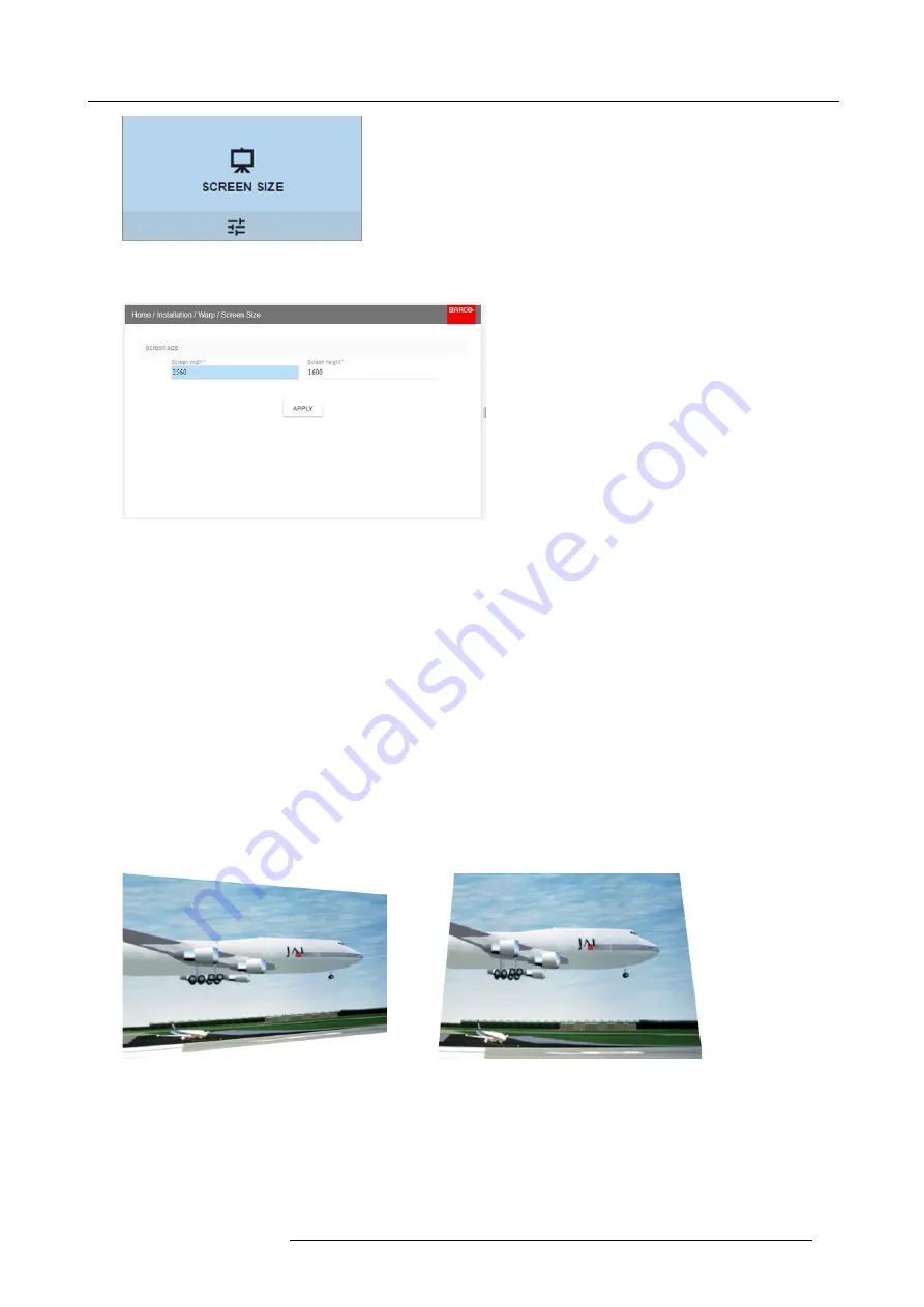
background image

8. Installation menu

Image 8-15
Warp Menu, Screen Size

The Screen Size menu is displayed.

Image 8-16

2. Select either

Screen width

or

Screen height

.

3. Set the screen size width and height to match the measurement of the screen.

Note:

It is only the ratio between the width and height that is used, so the values may be entered as the screen aspect ratio or
actual measurement in cm, inches or any other unit.

Tip:

A red border will be projected along with the current image. The border is a visual tool, showing the result of the adjusted
outline.

Tip:

The value can also be entered by the numeric keys on the remote control. Press * to delete existing numbers, and enter
the new value by the numeric keys.

4. Click

Apply

.

8.4.4

Warp – 4 Corners adjustment

About 4 Corners adjustment

Basically, this type of warping adjusts each of the four image corners in the X and Y direction, if you have a typical trapezoid picture
of the screen as shown below.

To have a successful Warp correction, the size of the screen must be entered. See "Warping – Screen Size", page 68

Some examples of pictures when the projector axis is not perpendicular to the screen.:

Image 8-17

How to adjust the image.

1. From the warp menu, select the 4 Corners Menu. A yellow frame will be visible.

601–426 F70 SERIES 24/10/2017

69

Содержание F90 - W13WUXGA

Страница 1: ...F70 Series User Manual 601 426 01 24 10 2017...

Страница 2: ...Barco Fredrikstad AS Habornveien 53 N 1630 Gamle Fredrikstad Norway Phone 47 6930 4550 Fax 47 6930 4580 Support Support fre barco com Visit us at the web www barco com Printed in Norway...

Страница 3: ...ames mentioned in this manual may be trademarks registered trademarks or copyrights of their respective holders All brand and product names mentioned in this manual serve as comments or examples and a...

Страница 4: ...d incorrectly or if after the transfer of risks the goods are subject to influences not agreed upon in the contract all guarantee claims of the purchaser will be rendered invalid Not included in the g...

Страница 5: ...ctor panel 22 2 10 Color Wheels 23 2 11 Optional Accessories 23 3 Lenses 25 3 1 Approved Lenses 25 3 2 Lens range 25 3 3 Replace a lens 27 3 4 Lens shift 29 3 5 Adjust zoom and focus 29 3 6 Adjust Iri...

Страница 6: ...g 66 8 4 2 Warping On Off 67 8 4 3 Warping Screen Size 68 8 4 4 Warp 4 Corners adjustment 69 8 4 5 Warping Bow 70 8 4 6 Warping Warp files 74 8 5 Blending 75 8 5 1 Basic Blend 75 8 5 2 Set up the syst...

Страница 7: ...s 3R laser product up to throw ratio 2 33 The projector conforms with IEC 60825 1 2007 and with performance standards for laser products under 21 CFR 1040 except with respect to those characteristics...

Страница 8: ...thoroughly and retain it for future reference Installation and preliminary adjustments should be performed by properly trained and qualified personnel All warnings on the projector and in the document...

Страница 9: ...d any liquid or solid object fall into the cabinet unplug the set and have it checked by qualified service personnel before resuming operations Do not disassemble this projector always take it to an a...

Страница 10: ...nt projector damage To ensure correct airflow is maintained the projector should only be operated when all of its covers in place Always remove lens cap before switching on the projector If the lens c...

Страница 11: ...e lens with throw ratio greater than 2 33 is installed Refer to the product manual for the lens list and throw ratio before operation Do not look directly in to the beam from the projector lens No dir...

Страница 12: ...he ceiling or through the use of physical barriers For applications installed in the USA market the above limits for cinema like environments do not apply The relevant minimum separation height is 2 5...

Страница 13: ...the HD The projector is also suitable for rear projection applications projecting a beam onto a defuse coated projection screen As displayed in image 1 3 two areas should be considered the restricted...

Страница 14: ...e restricted zone related to the rear reflection from the screen HDreflection also taking into account a 1 meter lateral separation The HDreflection distance equals 25 of the difference between the de...

Страница 15: ...d for consumer use This projector may become RG3 when an interchangeable lens with throw ratio greater than 3 15 is installed Refer to the manual for the lens list and hazard distance before operation...

Страница 16: ...Caution For North America With interchangeable lens with throw ratio greater than 2 5 consider hazard distance and installation requirements for RG3 product Refer User Manual Caution With Interchange...

Страница 17: ...te Turkey RoHS compliance T rkiye Cumhuriyeti AEEE Y netmeli ine Uygundur Republic of Turkey In conformity with the WEEE Regulation 1 8 Contact adresses For Taiwan Barco ltd 33F No 16 Xinzhan Rd Banqi...

Страница 18: ...1 Safety 14 601 426 F70 SERIES 24 10 2017...

Страница 19: ...s Light Power on Standby button backlight indications LCD panel Local keypad Remote Control Projector Address Connector panel Color Wheels Optional Accessories 2 1 Main Components Naming Conventions L...

Страница 20: ...l error or high temperature the LED will illuminate red By critical error the projector cannot be restarted until the projector is disconnected from the power supply and then reconnected again If the...

Страница 21: ...addition to access to the menu system The keypad and remote control functions are equal The keypad has a back light that can be switched on and off manually The light turns off automatically after a p...

Страница 22: ...es are not placed in the remote control unit to avoid control operation in its package resulting in a shorter battery life time At delivery the batteries can be found in a separated bag attached to th...

Страница 23: ...th two different protocols RC5 and NEC Depending on the projector to control the remote control can be switched between these protocols Which protocol to use The NEC protocol have to be used for Barco...

Страница 24: ...is a full feature wireless remote control powered by two 2 standard AA batteries The battery com partment is on the back side of the remote control The remote control is backlit for use in dark enviro...

Страница 25: ...nector Panel In this mode the projector will not be affected by signals from other non wired remote controls When using wired remote control the broadcast address must be set to Generic ID 0 See the m...

Страница 26: ...ween 0 and 31 Tip A few examples To enter address 3 press 3 digit button on the RCU to set the RCU s address to 3 and wait until the button pressed indicator is out Alternatively you can also press 0...

Страница 27: ...cations Other colorwheels are available upon request Consult Barco sales office or a service partner in order to find the most suitable colorwheel for the specific application 2 11 Optional Accessorie...

Страница 28: ...is a custom designed container that is suitable for shipping the projector including flight frame signal and power cords and up to two lenses The case is fully lined to protect the projector and lens...

Страница 29: ...1 FLD Short Focus 0 8 1 21 1 EN46 approved approved R9801295 FLD 0 65 1 EN47 approved approved PN_EN58 FLD 0 28 1 EN58 approved approved This projector may become Risk Group 3 RG3 when an interchangea...

Страница 30: ...3 2 48 1 2 0 15 FLD Lens 0 74 1 EN12 2 1 Yes 2 1 6 5 16 35 0 5 5 FLD Lens 1 24 1 6 1 EN13 2 1 2 22 Yes 2 1 6 5 1 3 25 59 33 24 1 0 15 FLD Lens 2 37 3 79 1 EN14 2 1 2 72 Yes 2 1 6 5 1 6 49 1 78 6 3 0 3...

Страница 31: ...6 12 0 7 7 FLD Lens 1 2 1 7 1 EN43 2 4 2 7 Yes 2 4 6 5 1 42 23 95 34 02 1 5 15 FLD NV Lens 1 2 1 7 1 NV43 2 4 2 7 Yes 2 4 6 5 1 42 23 95 34 02 1 5 15 FLD Lens 2 5 4 6 1 EN44 2 1 2 93 Yes 2 1 6 5 1 85...

Страница 32: ...arking on the bayonet is facing upwards 5 Position the lens bayonet into the projector lens mount and support in place with one hand 6 Slide the lens lever to the far right 7 Verify that the lens is f...

Страница 33: ...om and focus adjustments are motorized You can use the remote control local keypad OSD and or RS 232 commands to adjust the lens zoom and focus positions Not all lenses have zoom or iris control The m...

Страница 34: ...3 Lenses Image 3 6 Use the arrow keys to adjust Iris until preferred rendering is obtained 30 601 426 F70 SERIES 24 10 2017...

Страница 35: ...Confirm that the installation area meets all technical and environmental requirements See Installation conditions page 31 2 Decide where the projector will be mounted See Positioning the projector pag...

Страница 36: ...mance to local codes Hardware wire sizes and conduit types must comply with local codes Ventilation The free space necessary between the air intake and exhaust are shown below 1000 mm 500 mm Image 4 1...

Страница 37: ...om the screen Wherever possible the projector lens surface should be positioned so that it is perfectly perpendicular to the center of the screen Use the projector offset lens shift rather than physic...

Страница 38: ...projector shall be mounted in other ways than on the feet on a flat surface The threaded hole in the lower back end of the projector is NOT suitable for lifting or other heavy operations Only for adju...

Страница 39: ...shock It may also be necessary to use additional custom means to stabilize the projection lens to make sure that the projected image remains in position and properly focused 4 6 Projector safe attachm...

Страница 40: ...wing graphs illustrate the image size W and projection distance D for each of the projector lenses Tolerances are typically 5 due to optical lens variation Throw distance FLD WUXGA Projection distance...

Страница 41: ...4 00 4 50 5 00 5 50 6 00 6 50 7 00 7 50 3 50 0 00 Image height F L D L e n s 0 8 1 E N 4 2 0 7 7 m FLD Lens 1 7 2 5 1 EN41 1 5 15m FLD Lens 2 5 4 6 1 EN44 2 5 25 m FLD Lens 1 2 1 7 1 EN43 1 5 15m FLD...

Страница 42: ...ent What is Scheimpflug The lens holder has to be adjusted so that the sharp focus plane of the projected image falls together with the plane of the screen Fp1 Fp2 This is achieved by changing the dis...

Страница 43: ...ng will be required to solve the distortion The disadvantage of Masking is loss of content Therefore it is strongly recommended to place the projector in parallel with the projection screen and use th...

Страница 44: ...tally normal 2 F Image 4 10 4 Adjust the top Scheimpflug adjustment screw reference 3 until the test image in the bottom half of the screen is in focus Use a size 4 hex key to do this Note This proces...

Страница 45: ...ions Connector specifications Control interfaces 5 1 1 Making connections The source switching time varies from 0 5 to 5 seconds Source signal connectivity The connector panel at the back of the proje...

Страница 46: ...Max cable length 15 m 24 AWG RBR 2 m 24 AWG HBR1 HBR2 Supported Link Rate RBR HBR1 HBR2 Scan format Progressive Max input data resolution 2560x1600 120Hz WQXGA 3840x2400 60Hz 4K Max Bit depth 8 10 12...

Страница 47: ...m Cat6a 7 Pixel Clock 225HHz Video Datarate 5 3Gbps Max TMDS Clock Frequency 270 MHz Max video resolution supported 1920x1200 60Hz WUXGA 60Hz HDCP Pass Through Yes from Source to Projector IR Extensi...

Страница 48: ...he projector using the keypad or remote 1 Connect the line cord to the projector 2 Plug the 3 pronged cord into a grounded AC outlet The projector will begin warming up and the backlight of the Standb...

Страница 49: ...f the startup screen and info screens can be changed with Projector Toolset with an installed F70 F90 series plug in Description Plug the 3 prong plug of power cord into a grounded AC outlet The proje...

Страница 50: ...h the same booting phase as on power plugging then do the transition from READY to ON Of course startup time will be longer then from READY to ON 5 5 Power modes General The table below details the F7...

Страница 51: ...K button to select a menu topic and get more options Use the numeral keys to enter values or use the arrow keys to move the barscale up or down Press MENU again to exit the menu system Press the OSD b...

Страница 52: ...5 Getting started 48 601 426 F70 SERIES 24 10 2017...

Страница 53: ...relevant input connector icon to swap or activate the source The icon for the active source is highlighted The list of displayed sources can be adjusted to include other connectors The default selecti...

Страница 54: ...ce 2 Press OK The Select Source menu is displayed with the actual available sources filled out 3 Scroll down to the bottom of the list of available sources and select Connector Settings Image 6 3 Sour...

Страница 55: ...and DP2 To enable this mode select the source that fits in the menu Home Source Dual input modes There are four ways to connect dual input Dual Displayport Columns Dual Displayport Sequential Dual DVI...

Страница 56: ...Column Input 2 Dual Column Input1 2400 2400 1920 1920 3840 Image 6 6 Dual Column Setup Dual Sequential Input 2 Dual Sequential Input1 2400 3840 2400 3840 Image 6 7 Dual sequential setup 52 601 426 F70...

Страница 57: ...the contrast ratio of the displayed image by applying gain to the red green and blue signals Available range 0 00 to 2 00 Default value 1 00 Image 7 1 Image 7 2 When inside this menu it is possible to...

Страница 58: ...more vivid the color display will be Available range 1 00 to 2 00 Default value 1 00 Image 7 4 7 4 Sharpness About The sharpness adjustment amplifies the high frequency components in the picture meani...

Страница 59: ...sting the amount of gamma compensation changes you change only the perceived brightness levels Different types of displays have different gamma factors that need to be corrected in order to look and b...

Страница 60: ...h how adjusting the Colors to a specific setting there are also a certain number of presets available which forces the color output to specific color standards The selection of the presets will vary d...

Страница 61: ...on the R G and B coordinates Custom RGBCMY 6 point color configuration both RGB and CMY In RGBCMY mode each color can be given a specific coordinate within the measured color triangle Custom WHITE Con...

Страница 62: ...e 41 regarding use of input sources in 4K mode Image 7 15 Output resolution menu 7 6 3 Smear Reduction About Smear is a phenomenon that typically occur when objects in the picture moves in high speed...

Страница 63: ...olor intensity and by that also the perceived light intensity Enter the menu and select the option that give the best result Image 7 18 This menu is only valid for COLOR colorwheel in WQXGA 60Hz mode...

Страница 64: ...mic Range HDR content with a luminance level of up to 10 000 cd m and can be used with the Rec 2020 color space If your provided HDR content has been mastered with PQ e g Dolby Vision or HDR10 you can...

Страница 65: ...7 Image menu 2 Select the desired Unit nits or foot lambert 3 Enter the Screen luminance either in nits or foot lambert 601 426 F70 SERIES 24 10 2017 61...

Страница 66: ...7 Image menu 62 601 426 F70 SERIES 24 10 2017...

Страница 67: ...c rendering of the environment This will visualize in a realistic way night time dusk and dawn and limited visibility scenarios The IR light source has a wavelength of 740nm How to enable IR Night Vis...

Страница 68: ...IR LED will be dominant and the image on the screen will be visible with the Night Vision Goggles Put on the goggles and adjust the IRLED slider to obtain an optimal night vision rendering Image 8 4 B...

Страница 69: ...rrows left and right to adjust focus Shift Installation Lens Shift Use the left right up and down navigational arrows to adjust the lens shift in four directions 8 3 Orientation About Installation Ori...

Страница 70: ...positions and press OK button to activate 8 4 Warping 8 4 1 About Warping About Image warping is the process of digitally manipulating an image to compensate for the distortion of the screen typicall...

Страница 71: ...rping On Off About warping on off By toggling between on and off the warping functionality can be enabled or disabled How to toggle 1 In the main menu select Installation Warp Image 8 10 Installation...

Страница 72: ...age information but also the black bars If we want to position e g the active left top corner exactly on the screen using 4 corner warp then it is very hard to do that as we are moving the black left...

Страница 73: ...ne Tip The value can also be entered by the numeric keys on the remote control Press to delete existing numbers and enter the new value by the numeric keys 4 Click Apply 8 4 4 Warp 4 Corners adjustmen...

Страница 74: ...nates for each corner When the warping is complete exit the menu Image 8 19 4 If the picture still has a trapezoid shape warp is not enabled Select the Installation Warp menu and press enter The slide...

Страница 75: ...lation menu Warp 2 In the Warp menu select Bow Image 8 23 Warp menu Bow A check symbol at the bottom right corner indicates that the bow function is activated 3 To enable Bow correction make sure the...

Страница 76: ...each side of the center of the highlighted side When corrected with the values in the image above the picture will occur as shown below Repeat this step for all sides of the picture that has to be cor...

Страница 77: ...below Observe that the upper side of the picture now has an asymmetric correction Image 8 28 Asymmetric bow correction 4 Repeat the step for each side of the picture that must be corrected Definition...

Страница 78: ...ile endpoint directly via the curl program or some other tool that supports http upload For more information on uploading downloading Warp files using the Projector Toolset refer to the Projector Tool...

Страница 79: ...ated This blend function ensures a seamless transition of the images between the two projectors The principle is that the light intensity in the blend zone from each projector will be adjusted individ...

Страница 80: ...ls the width of the blend zone for the projector also must be set to 500 pixels First step is to align the image from the projectors as accurate as possible in a mechanical way meaning without any opt...

Страница 81: ...ote control Adjustment procedure in over under configuration For Blend adjustments in over under configuration the procedure is the same as for side by side but use the Top and Bottom height instead a...

Страница 82: ...keys on the remote control 5 Repeat the same procedure for the other projector 6 Disable the Show lines when the Black level adjustment is completed 8 5 5 Black Level Files About custom Black Level Fi...

Страница 83: ...he projector This is a timesaving option when multiple projectors need an identical blending configuration To upload or download Blend masks you can use the Prospector tool Alternatively you can conta...

Страница 84: ...lable select the desired file Image 8 45 3 Click on the on off button on top to activate the selected Blend file 8 6 Illumination About Home Installation Illumination Power Review light source status...

Страница 85: ...ination Menu The actual illumination setting is indicated in the menu Enter the menu and use the slider to adjust Image 8 47 8 7 Display Setup About Described in other topics related to projector vers...

Страница 86: ...8 Installation menu 82 601 426 F70 SERIES 24 10 2017...

Страница 87: ...Static mode Set address subnet mask and default gateway according to network specification DHCP mode Assigned IP address subnet mask and gateway Image 9 1 Manually set up the IP adress Go to the menuS...

Страница 88: ...ect System Settings Standby ECO Image 9 3 2 To disable the ECO mode make sure the slider is set to Off The slider is disabled when set to the left and when it becomes grey 9 4 Service About System set...

Страница 89: ...et to native ImageStereo Sync delay 0 s Swap eye Off Dark time lowest value available ImageDisplay Display mode AutoStereo ImageOrientation Orientation Table Front ImageSource Source files Standard Im...

Страница 90: ...order to prevent unintentional lens adjustments especially after e g a completed setup and adjustment there is a possibility to disable certain lens adjustment functions These functions are directly a...

Страница 91: ...u only No changes can be made to settings from this menu Overview Status menu overview 10 1 Status menu overview Status menu While in the main menu press Status Image 10 1 Status Menu enter Image 10 2...

Страница 92: ...oftware package version Model name Projector model name Illumination Shows the used light source power in and runtime Communication Lists the projector network address the remote control broadcast add...

Страница 93: ...sed when DVI source is used For Displayport source the sync signal is present in the signalcable but external sync can also be used when necessary Passive stereo input Use two channel input two cables...

Страница 94: ...double picture or a shade of the picture from the other side shall not be observed Repeat for both sides and adjust the Sync Delay slider until a clean picture is visible in each eye If the 3D pictur...

Страница 95: ...device from the computer Place the projector in Standby mode status indicator is steady White Insert the USB Stick in to the USB port on the projector After a few seconds the status indicator will fl...

Страница 96: ...12 User Maintenance 92 601 426 F70 SERIES 24 10 2017...

Страница 97: ...aning the projector cabinet exterior only Clean the housing of the projector with a damp cloth Stubborn stains may be removed with a cloth lightly dampened with a mild detergent solution 13 3 Filters...

Страница 98: ...13 Cleaning the projector 94 601 426 F70 SERIES 24 10 2017...

Страница 99: ...ns Motorized zoom focus vertical and horizontal shift iris and shutter Color correction P7 RealColorTM CLO constant light output Yes Light source Laser phosphor Light source lifetime Up to 60 000 hour...

Страница 100: ...ess 5 500 8 000 lumens Contrast ratio 1 800 1 sequential 50 000 1 dynamic IR for NVG no Brightness uniformity 90 Aspect ratio 16 10 Projector type 1DLP laser phosphor Resolution 1 920 x 1 200 WUXGA Le...

Страница 101: ...ts and labor Extendable up to 5 years Notes SW upgradable Please contact an authorized Barco representative for details 14 3 FS70 4K6 Brightness 5 000 center lumens Contrast ratio 1800 1 sequential 50...

Страница 102: ...ity 20 80 RH Storage humidity 10 90 RH Dimensions WxLxH 475 x 593 x 286 mm 18 7 x 23 3 x 11 2 in Weight 37 kg 81 5 lbs Standard accessories Power cord wireless remote control Certifications CE FCC Cla...

Страница 103: ...600 120Hz Software tools Projector Toolset Control IR RS232 RJ45 Network connection IR RS232 RJ45 Power requirements 100 240V 50 60Hz Power consumption 1 100 W Max BTU per hour Max 4 000 BTU h Noise...

Отзывы: