24. Lens shift assembly
24.4 Lens Lock screws
4 screws for locking lens follows unit as accessories. Screws can be ordered separately: 5xx-xxxx-xx
Image 24-6
24.5 Scheimp
fl
ug screws
Lock nut and adjustment screws are separately available order:
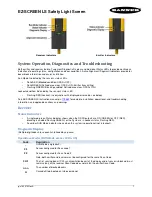
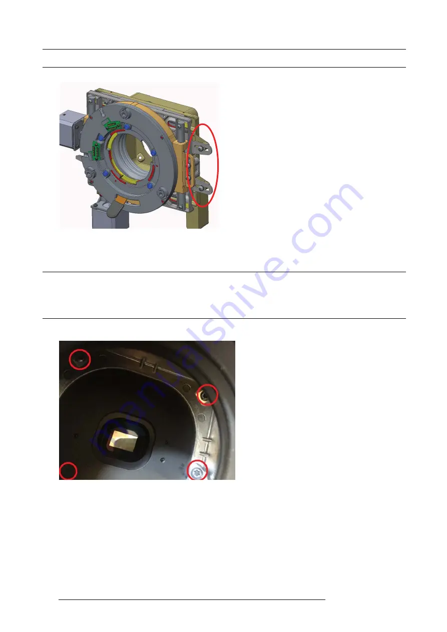
24.6 Lens shift assembly and optical actuator
1. Remove 4 screws (TX20 M4x12) available from inside lens opening.
Image 24-7
2. Remove 2 screws (TX20 M4x12) securing the assembly to the base plate and remove the complete assy.
126
723–0016 F90 01/12/2017
Содержание F90 series
Страница 1: ...F90 Service Manual 723 0016 02 01 12 2017...
Страница 6: ...Table of contents 4 723 0016 F90 01 12 2017...
Страница 8: ...1 Introduction 6 723 0016 F90 01 12 2017...
Страница 10: ...2 General safety 8 723 0016 F90 01 12 2017...
Страница 18: ...4 DLP System General Description 16 723 0016 F90 01 12 2017...
Страница 25: ...5 GP6 system functional description Image 5 5 723 0016 F90 01 12 2017 23...
Страница 28: ...5 GP6 system functional description 26 723 0016 F90 01 12 2017...
Страница 34: ...7 OSD display menu 32 723 0016 F90 01 12 2017...
Страница 36: ...8 Thermal management system Image 8 1 34 723 0016 F90 01 12 2017...
Страница 42: ...8 Thermal management system 40 723 0016 F90 01 12 2017...
Страница 58: ...14 XPS actuator 56 723 0016 F90 01 12 2017...
Страница 60: ...15 Light engine 58 723 0016 F90 01 12 2017...
Страница 82: ...18 Assembly Hierarchy 80 723 0016 F90 01 12 2017...
Страница 103: ...20 Scheduled operations Image 20 42 Image 20 43 723 0016 F90 01 12 2017 101...
Страница 104: ...20 Scheduled operations 102 723 0016 F90 01 12 2017...
Страница 112: ...21 DMD DMD Board CLGA DMD heatsink elements 110 723 0016 F90 01 12 2017...
Страница 132: ...24 Lens shift assembly 130 723 0016 F90 01 12 2017...
Страница 134: ...25 Prism Housing Image 25 5 132 723 0016 F90 01 12 2017...