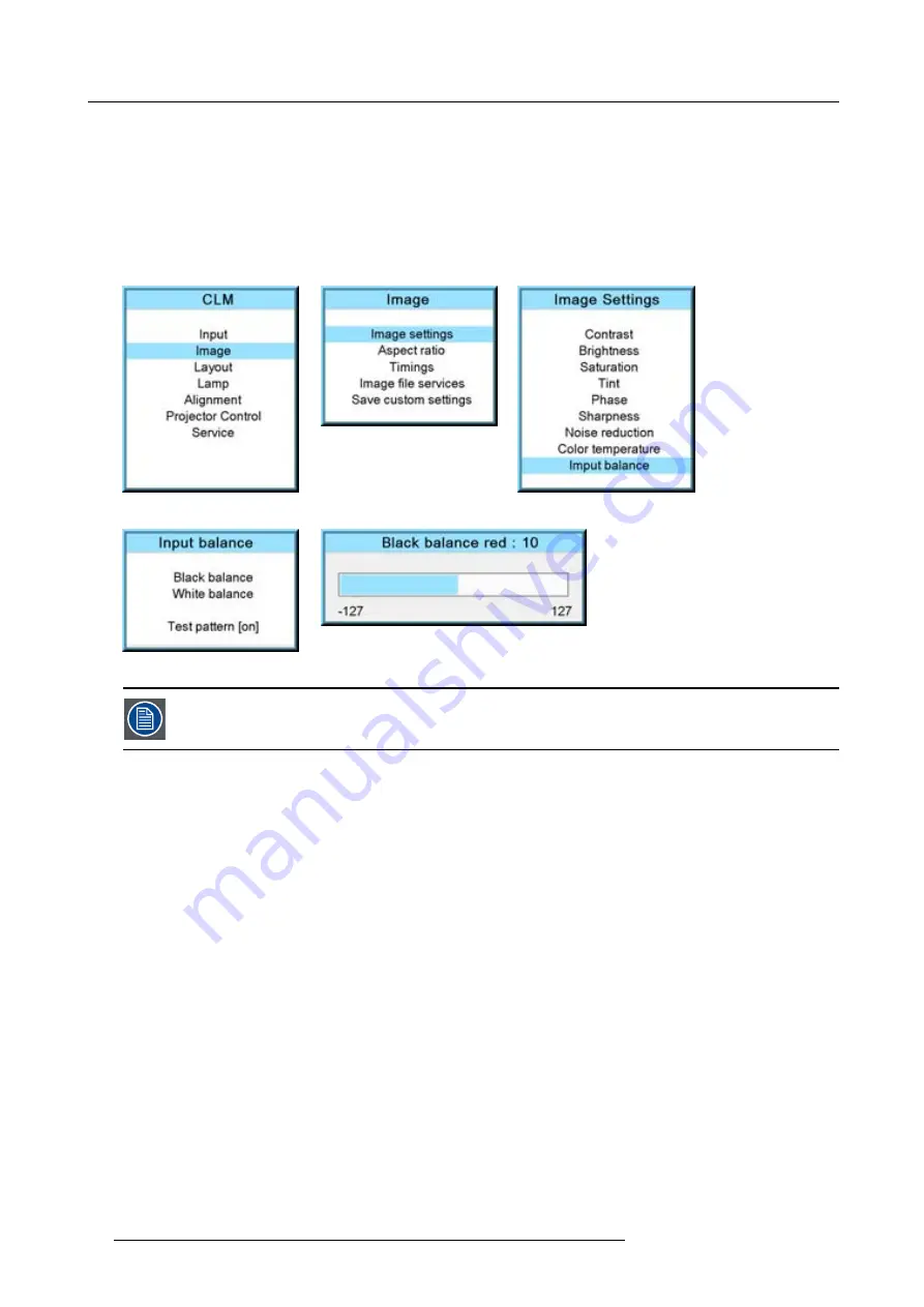
9. Image menu
9. Toggle with
▲
or
▼
key to
Black balance blue
and adjust the blue black level on a minimal value.
Note:
This minimal value is not necessary , provided that the 2 other colors are not in
fl
uencing too much the color to be adjusted,
in fact the aim is to minimize the effect of the two other colors since there is a risk of reaching too soon the 50% transition
due to the contribution of these two other colors signals.
10.Toggle with
▲
or
▼
key to
Black balance green
and adjust the Green black level until bright spots appear on the screen.
11.Toggle with
▲
or
▼
key to
Black balance blue
adjust the Blue black level until bright spots appear on the screen.
12.Toggle with
▲
or
▼
key to
Black balance red
adjust the Red black level until bright spots appear on the screen.
The projected image should now be noisy full black
Image 9-46
Image 9-47
Image 9-48
Image 9-49
Image 9-50
If one uses a gray scale pattern, the bright spots should appear in the black bar.
Performing White input balance
1. Connect the source you want to project.
2. Press
MENU
to activate the menus.
3. Use the
▲
or
▼
key to select
Image
and press
ENTER
.
4. Use the
▲
or
▼
key to select
Image settings
and press
ENTER
.
5. Use the
▲
or
▼
key to select
Input balance
and press
ENTER
.
6. Do you want to use an internally generated test pattern?
If yes, Use the
▲
or
▼
key to select
Test pattern
and press
ENTER
to toggle between [on] and [off]
If no, select a white pattern (or gray scale as alternative).
7. Use the
▲
or
▼
key to select
White balance
and press
ENTER
.
The white balance bar scale for a typical color is displayed.
8. Toggle with the
▲
or
▼
key to select
White balance red
. (image 9-51, image 9-52, image 9-53, image 9-54, image 9-55)
9. Adjust the red white level (gain) on a minimal value
10.Toggle with
▲
or
▼
key to
White balance blue
and adjust the blue white level (gain) on a minimal value.
Note:
This minimal value is not necessary , provided that the 2 other colors are not in
fl
uencing too much the color to be adjusted,
in fact the aim is to minimize the effect of the two other colors since there is a risk of reaching too soon the transition
(bright spots) due to the contribution of these two other colors signals.
11.Toggle with
▲
or
▼
key to
White balance green
and adjust the Green white level (gain) until bright spots appear on the screen.
12.Toggle with
▲
or
▼
key to
White balance blue
adjust the Blue white level (gain) until bright spots appear on the screen.
13.Toggle with
▲
or
▼
key to
White balance red
adjust the Red white level (gain) until bright spots appear on the screen.
The projected image should now be noisy neutral gray.
84
R59770021 CLM R10+ 11/10/2010
Содержание CLM R10+ R90501001
Страница 1: ...CLM R10 Users manual R9050100 R90501001 R90501005 R59770021 11 11 10 2010...
Страница 14: ...1 Safety 10 R59770021 CLM R10 11 10 2010...
Страница 22: ...2 General 18 R59770021 CLM R10 11 10 2010...
Страница 36: ...3 Physical installation 32 R59770021 CLM R10 11 10 2010...
Страница 41: ...4 Stacking CLM projectors Zoom Image 4 9 Zoom adjustment R59770021 CLM R10 11 10 2010 37...
Страница 42: ...4 Stacking CLM projectors 38 R59770021 CLM R10 11 10 2010...
Страница 50: ...5 Connections 46 R59770021 CLM R10 11 10 2010...
Страница 66: ...7 Start up of the Adjustment mode 62 R59770021 CLM R10 11 10 2010...
Страница 75: ...8 Input menu Image 8 26 Image 8 27 Image 8 28 R59770021 CLM R10 11 10 2010 71...
Страница 76: ...8 Input menu 72 R59770021 CLM R10 11 10 2010...
Страница 102: ...9 Image menu 98 R59770021 CLM R10 11 10 2010...
Страница 116: ...10 Layout menu Image 10 61 Image 10 62 Image 10 63 Image 10 64 112 R59770021 CLM R10 11 10 2010...
Страница 169: ...14 Service menu Image 14 55 Image 14 56 Image 14 57 R59770021 CLM R10 11 10 2010 165...
Страница 170: ...14 Service menu 166 R59770021 CLM R10 11 10 2010...
Страница 183: ...16 Servicing Image 16 15 Top up reservoir 2 cm Image 16 16 Pressurize circuit R59770021 CLM R10 11 10 2010 179...
Страница 184: ...16 Servicing 180 R59770021 CLM R10 11 10 2010...
Страница 194: ...17 Projector covers removal and installation 190 R59770021 CLM R10 11 10 2010...
Страница 202: ...C DMX Chart 198 R59770021 CLM R10 11 10 2010...
Страница 212: ...E Troubleshooting 208 R59770021 CLM R10 11 10 2010...
Страница 217: ...F Mounting optional Carry handle 1 2 3 1 4 5 Image F 7 Image F 8 R59770021 CLM R10 11 10 2010 213...
Страница 218: ...F Mounting optional Carry handle 214 R59770021 CLM R10 11 10 2010...
Страница 220: ...G Order info 216 R59770021 CLM R10 11 10 2010...
Страница 228: ...Index 224 R59770021 CLM R10 11 10 2010...


