12. Alignment menu
Image 12-31
When selecting a
fi
xed color space, the values of this selected color space overwrite the custom selected
color space.
12.10 White peaking
About white peak and brilliant color
In video centric applications true color reproduction is generally a priority over brightness. To achieve this a typical design will not
utilize a white segment of the color wheel. This has the side effect of reducing the amount of light allowed through the color wheel,
which reduces the overall brightness. To compensate for this a technique can applied called Spoke Light Capture (SLR). The spokes
are de
fi
ned to be the time between colors. If the light is passed through the spokes, the average over time across them is made up
of a mixture of the two adjacent colors. This will result in a secondary color. Color processing can take advantage of this situation.
Combining red with green yields yellow light. Similarly, combining red with blue yields magenta while combining blue with green
yields cyan. The BrilliantColor™ technology is con
fi
gured to process the spoke regions as a secondary color which improves the
brightness of the display and gives the viewer a truly life-like image.
If after all, the viewer is still not satis
fi
ed with the color reproduction, this can further be improved by diminishing the white peaking.
With the white peaking on 10 the full white segment is used in projecting the image. At the other end when the white peaking is
on 0, the white segment is cancelled out from the projected image. This makes the colors look more pronounced as with full white
peaking on.
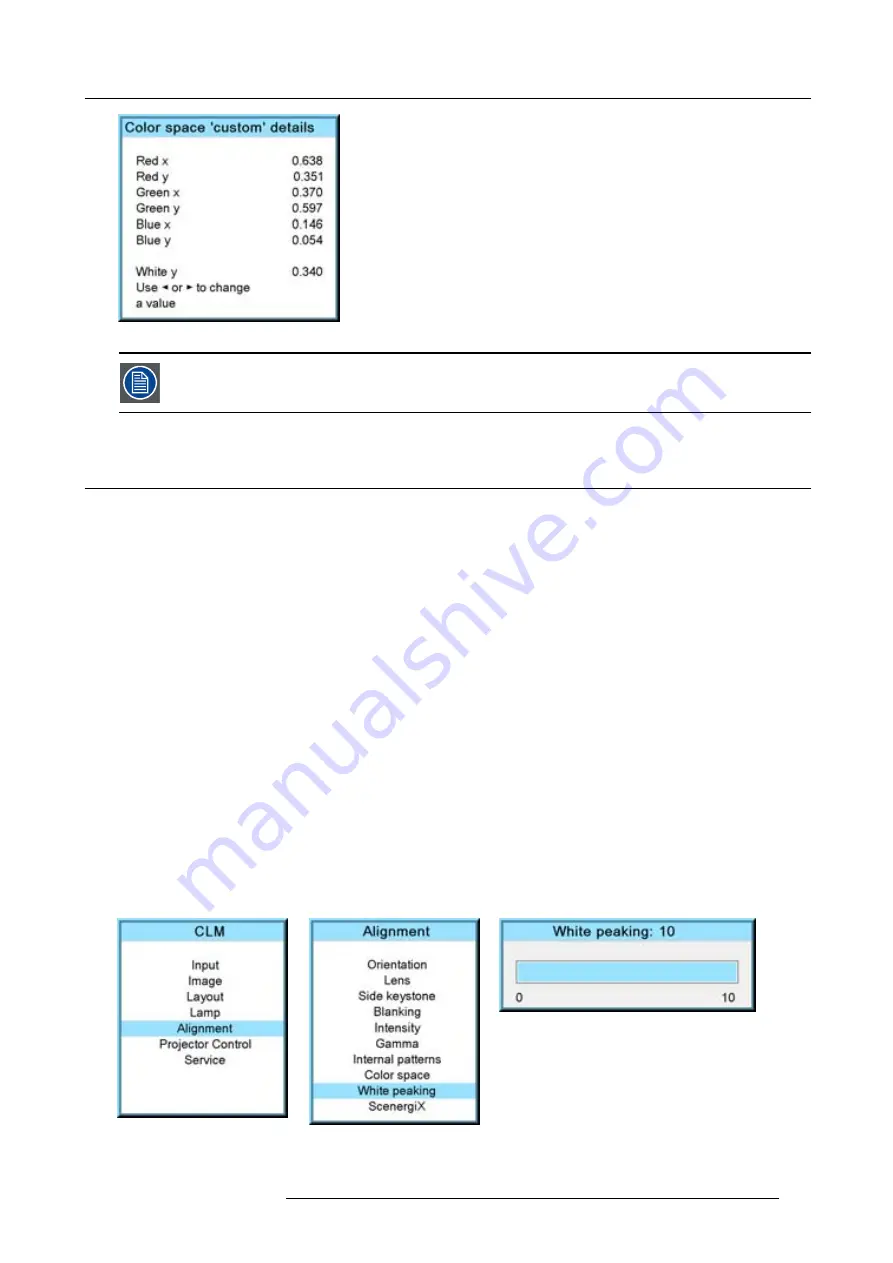
How to change the white peaking value
1. Press
MENU
to activate the menus.
2. Use the
▲
or
▼
key to select
Alignment
and press
ENTER
.
3. Use the
▲
or
▼
key to select
White peaking
and press
ENTER
.
4. Use
◄
or
►
key to change the white peaking setting and press
EXIT
.
White peaking can be set between 0 and 10.
The default value is 10.
With 0, no white peaking, spokes not used to enhance the secondary colors and 10, full white peaking, spokes are fully used to
enhance the secondary colors to show a truly life-like image.
Image 12-32
Image 12-33
Image 12-34
R59770021 CLM R10+ 15/03/2010
125
Содержание CLM R10+ R9050100
Страница 1: ...CLM R10 Users manual R9050100 R90501001 R59770021 10 15 03 2010 ...
Страница 14: ...1 Safety 10 R59770021 CLM R10 15 03 2010 ...
Страница 22: ...2 General 18 R59770021 CLM R10 15 03 2010 ...
Страница 35: ...3 Physical installation Skew Image 3 28 Skew adjustment R59770021 CLM R10 15 03 2010 31 ...
Страница 36: ...3 Physical installation 32 R59770021 CLM R10 15 03 2010 ...
Страница 48: ...5 Connections 44 R59770021 CLM R10 15 03 2010 ...
Страница 64: ...7 Start up of the Adjustment mode 60 R59770021 CLM R10 15 03 2010 ...
Страница 74: ...8 Input menu 70 R59770021 CLM R10 15 03 2010 ...
Страница 115: ...10 Layout menu Image 10 61 Image 10 62 Image 10 63 Image 10 64 R59770021 CLM R10 15 03 2010 111 ...
Страница 116: ...10 Layout menu 112 R59770021 CLM R10 15 03 2010 ...
Страница 158: ...13 Projector control 154 R59770021 CLM R10 15 03 2010 ...
Страница 172: ...14 Service menu 168 R59770021 CLM R10 15 03 2010 ...
Страница 186: ...16 Servicing 182 R59770021 CLM R10 15 03 2010 ...
Страница 195: ...17 Projector covers removal and installation Image 17 18 Secure the lamp door R59770021 CLM R10 15 03 2010 191 ...
Страница 196: ...17 Projector covers removal and installation 192 R59770021 CLM R10 15 03 2010 ...
Страница 204: ...C DMX Chart 200 R59770021 CLM R10 15 03 2010 ...
Страница 210: ...D Specifications 206 R59770021 CLM R10 15 03 2010 ...
Страница 216: ...E Troubleshooting 212 R59770021 CLM R10 15 03 2010 ...
Страница 222: ...F Mounting optional Carry handle 218 R59770021 CLM R10 15 03 2010 ...
Страница 224: ...G Order info 220 R59770021 CLM R10 15 03 2010 ...
Страница 232: ...Index 228 R59770021 CLM R10 15 03 2010 ...


