background image

29

R5911705 /02

Bragi

2.3 Locking the lens position

About

The projector has the feature of mechanically lock the lens position in both horizontal and vertical position.

This is particularly important in moving platform applications in order to avoid that the lens comes out of
position during operation. This topic describes the procedure for this operation.

CAUTION:

It is of great importance to disable the Lens Shift function when the mechanically lens lock is
performed. If not, the shift mechanism will be possible destructed if lens shift accidentally is
performed from the remote control, keypad, and also via API command, when the mechanism is
mechanically locked.

Tools needed

Screwdriver Tx25

Wrench or Socket wrench 8mm, OR allen key 4mm

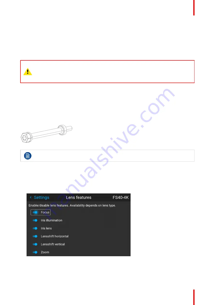
Lens lock screw

The lens lock screws has a special design that allows use of two different tools for tightening; 4mm Allen key
or 8mm wrench.

Image 2

4 Lens lock screw

Maximum tightening torque: 2.0 Nm.

Lens lock procedure.

1.

Move the lens to the optimal horizontal and vertical position.

2.

Disable the lens shift function by entering the menu

Home / System Settings / Service / Lens features

Select the function to disable by the arrow keys, and disable the function by pressing the OK button.

Image 2

5

3.

Release 8 screws in front of the projector indicated in the figure below.

Remove the front cover

Lenses

Содержание Bragi

Страница 1: ...ENABLING BRIGHT OUTCOMES Installation Guide Bragi ...

Страница 2: ...red office Barco NV President Kennedypark 35 8500 Kortrijk Belgium www barco com en support www barco com Barco Fredrikstad AS Habornveien 53 N 1630 Gamle Fredrikstad Norway Support fre barco com www barco com ...

Страница 3: ...rence at his own expense Changes or modifications not expressly approved by the party responsible for compliance could void the user s authority to operate the equipment FCC responsible Barco Inc 3059 Premiere Parkway Suite 400 30097 Duluth GA United States Tel 1 678 475 8000 Trademarks Brand and product names mentioned in this manual may be trademarks registered trademarks or copyrights of their ...

Страница 4: ...e are system failures which are attributed to programs or special electronic circuitry provided by the purchaser e g interfaces Normal wear as well as normal maintenance are not subject to the guarantee provided by Barco either The environmental conditions as well as the servicing and maintenance regulations specified in this manual must be complied with by the customer Copyright All rights reserv...

Страница 5: ...lace a lens 27 2 3 Locking the lens position 29 3 Physical installation 31 3 1 Installation process 32 3 2 Installation conditions 33 3 3 Initial inspection 35 3 4 Positioning the projector 36 3 5 Mounting the projector general considerations 37 3 6 Mounting surfaces 38 3 7 Projector safe attachment points 39 3 8 Removal of the front cover 41 3 9 Throw distance 42 3 10 Scheimpflug Boresight adjust...

Страница 6: ... 74 5 Source menu 75 5 1 Connector selection 76 5 2 Connector settings 77 5 3 Using dual inputs 80 6 Image menu 81 6 1 Contrast 83 6 2 Brightness 84 6 3 Saturation 85 6 4 Sharpness 86 6 5 Gamma adjustment 87 6 6 Gamma Types 88 6 6 1 Predefined Gamma types 89 6 7 Digital Zoom Shift 90 6 7 1 Digital Zoom 91 6 7 2 Digital Shift 92 6 8 Advanced image adjustments 93 6 8 1 P7 Realcolor 94 6 8 2 Edit the...

Страница 7: ...cedure 140 8 5 4 Basic blend setup procedure 141 8 5 5 Black level setup procedure 143 8 5 6 Color level adjustment procedure 145 8 5 7 Black level files 146 8 5 8 Blend files 147 8 5 9 Advanced blend 148 8 5 10 CLO Constant light output 149 8 6 Illumination 150 8 7 IG pixel shift 151 8 7 1 IG pixel shift 152 8 7 2 AutoStereo 3D Setup 153 9 GUI Profiles 155 9 1 Profiles introduction 156 9 2 Profil...

Страница 8: ...R5911705 02 Bragi 8 10 12 Lens calibration 178 10 13 Controlling the backlight of the LCD Display 179 11 GUI Status menu 181 11 1 Status menu overview 182 12 3D 185 Index 187 ...

Страница 9: ...you understand and follow all safety guidelines instructions and warnings included in this chapter and this manual Clarification of the term Bragi series used in this document Use in this document of the term Bragi means that the content is applicable for the following products Bragi CS Defining the Bragi platform The Bragi series products in general are all products within the Barco GP5 platform ...

Страница 10: ...safety regulation world wide The safety standard covers information technology equipment including electrical business equipment intended to operate in normal environments offices and homes This safety standard imposes important requirements on the use of safety critical components materials and insulation in order to protect the user or operator against risk of electric shock and energy hazard an...

Страница 11: ...ector Should any liquid or solid object fall into the cabinet unplug the set and have it checked by qualified service personnel before resuming operations Do not disassemble this projector always take it to an authorized trained service person when service or repair work is required Do not use an accessory attachment which is not recommended by the manufacturer Lightning For added protection for t...

Страница 12: ...the projector If the lens cap is not removed it may melt due to the high energy light emitted through the lens Melting the lens cap may permanently damage the surface of the projection lens Only connect the projector to signal sources and voltages as described in the technical specification Connecting to unspecified signal sources or voltages may lead to malfunction and permanent damage of the uni...

Страница 13: ...ipment If the product has been exposed to rain or water If the product does not operate normally when the operating instructions are followed Adjust only those controls that are covered by the operating instructions since improper adjustment of the other controls may result in damage and will often require extensive work by a qualified technician to restore the product to normal operation If the p...

Страница 14: ...ired to take adequate measures This device complies with part 15 of the FCC Rules Operation is subject to the following conditions 1 This device may not cause harmful interference and 2 this device must accept any interference received including interference that may cause undesired operation This Class A digital apparatus complies with Canadian ICES 003 Cet appareil numerique de Ia classe est con...

Страница 15: ...ng conditions 1 This device may not cause harmful interference and 2 this device must accept any interference received including interference that may cause undesired operation This Class A digital apparatus complies with Canadian ICES 003 Cet appareil numerique de Ia classe est conforme à Ia norme NMB 003 du Canada EMC FCC CANADA 此為甲類資訊技術設備 於居住環境中使用時 可能會造成射頻擾動 在此種情況下 使用者會被要求採取某些適當的對策 警告使用者 RG2 IE...

Страница 16: ... from other types of waste and recycle them responsibly to promote the sustainable reuse of material resources For more information about recycling of this product please contact your local city office or your municipal waste disposal service For details please visit the Barco website at http www barco com AboutBarco weee WEEE Information This product conforms to all requirements of the EU Directi...

Страница 17: ...911705 02 Bragi 1 6 Turkey RoHS compliance Turkey RoHS compliance Türkiye Cumhuriyeti AEEE Yönetmeliğine Uygundur Republic of Turkey In conformity with the WEEE Regulation Safety and environment information ...

Страница 18: ...醚 PBDE 印制电路配件 Printed Circuit Assemblies X O X O O O 外接电 线 缆 External Cables X O O O O O 內部线路 Internal wiring X O O O O O 镜头支架 Lensholder X O O O O O 螺帽 螺钉 栓 螺旋 钉 垫圈 紧固 件 Nuts bolts screws washers Fasteners X O O O O O 电源供应器 Power Supply Unit X O O O O O 风扇 Fan X O O O O O 附電池遙控器 Remote control X O O O O O 本表格依据SJ T 11364的规定编制 This table is prepared in accordance with the provisions of SJ T 11364 ...

Страница 19: ...rdous substances in electrical and electronic product of Chinese Mainland marked with the Environmental Friendly Use Period EFUP logo The number inside the EFUP logo that Barco uses please refer to the photo is based on the General guidelines of environment friendly use period of electronic information products of Chinese Mainland Safety and environment information ...

Страница 20: ...shers Fasteners O O O O O 電源供應器 Power Supply Unit O O O O O 風扇 Fan O O O O O 遙控器 Remote control O O O O O 備考1 超出0 1 wt 及 超出0 01 wt 係指限用物質之百分比含量超出百分比含量基準值 Note 1 Exceeding 0 1 wt and exceeding 0 01 wt indicate that the percentage content of the restricted substance exceeds the reference percentage value of presence condition 備考2 〇 係指該項限用物質之百分比含量未超出百分比含量基準值 Note 2 〇 indicates that the percentage con...

Страница 21: ...ess 新北市板橋區新站路16號33樓 傳真 Fax 02 7715 0298 電話 Tel 02 7715 0299 E mail service taiwan barco com Importers contact information To find your local importer contact Barco directly or one of Barco s regional offices via the contact information given on Barco s web site www barco com Contact information Norway factory Barco Fredrikstad as Habornveien 53 N1630 Gamle Fredrikstad Norway Phone 476930 4550 Supp...

Страница 22: ...R5911705 02 Bragi 22 1 10 Production Address Factories Barco NV BELGIUM President Kennedypark 35 B 8500 Kortrijk Safety and environment information ...

Страница 23: ...23 R5911705 02 Bragi 1 11 Product Info Product info Image 1 2 product name 產品名稱 projector 投影機 model 型號 GP5 Safety and environment information ...

Страница 24: ...environment this equipment may cause radio interference Class A ITE Information Technology Equipment Warning This is a class A product In a domestic environment this product may cause radio interference in which case the user may be required to take adequate measures 警告使用者 此為甲類資訊技術設備 於居住環境中使用時 可能會造成射頻擾動 在此種情況下 使用者會 被要求採取某些適當的對策 Safety and environment information ...

Страница 25: ...25 R5911705 02 Bragi 2 1 Approved lenses 26 2 2 Replace a lens 27 2 3 Locking the lens position 29 Lenses 2 ...

Страница 26: ...D 3 8 6 5 1 R9801216 EN41 FLD 1 7 2 5 1 R9801226 EN42 FLD 0 8 1 R9801230 EN43 FLD 1 2 1 7 1 R9801211 EN44 FLD 2 5 4 6 1 R9801220 EN45 FLD Long Focus 0 8 1 21 1 R9801221 EN46 FLD Short Focus 0 8 1 21 1 R9801295 EN47 FLD 0 65 1 R9802241 EN61 FLDX 1 7 2 5 1 R9802242 EN63 FLDX 1 2 1 7 1 R9802243 EN66 FLDX 0 8 1 21 1 R9802244 EN67 FLDX 0 65 1 R9802232 EN68 FLD 0 28 1 R9801832 UST 90 FLDX 0 38 1 Lenses ...

Страница 27: ...functionality e g from a EN 63 to a EN42 lens it is recommended to power down and pull the AC cord This is because the memory of the iris position will not be reset but will show the position in LCD or OSD for the lens that was removed When rebooting the projector the memory will be reset The reverse scenario will happen when changing from a lens with no motorized positioning support to a lens wit...

Страница 28: ...nd from the lens Image 2 2 Remove a lens 1 Support the lens with one hand 2 Use the other hand to slide the lens release lever to the far left position 3 Pull the lens straight out of the projector lens mount 4 Replace with another lens or install the projector lens cap Image 2 3 Lenses ...

Страница 29: ...rom the remote control keypad and also via API command when the mechanism is mechanically locked Tools needed Screwdriver Tx25 Wrench or Socket wrench 8mm OR allen key 4mm Lens lock screw The lens lock screws has a special design that allows use of two different tools for tightening 4mm Allen key or 8mm wrench Image 2 4 Lens lock screw Maximum tightening torque 2 0 Nm Lens lock procedure 1 Move th...

Страница 30: ...ighten the screws indicated below Tighten the screws indicated by the red circles for locking the vertical movement Tighten the screws indicated by the blue circles for locking the horizontal movement Image 2 8 5 Reassemble the front cover Lenses ...

Страница 31: ... projector installation is unique and as such the information in this chapter is only provided as a guideline Likewise any images or graphical representations shown here are for illustrative purposes only If you require further information and assistance during the installation process contact a qualified projection technician or your local support office for advice CAUTION When the projector is i...

Страница 32: ...area meets all technical and environmental requirements 2 Decide where the projector will be mounted 3 Unpack the projector and confirm that all equipment is present and in good working order 4 Mount the projector 5 Install the projector lens 6 Connect the source 7 Power up the projector 8 Set up the image Physical installation ...

Страница 33: ...public of China the certified altitude is specified on the product label Mains power requirement Projector Power Requirement Projectors all in range 100 240V 60 50 Hz To protect operating personnel the National Electrical Manufacturers Association NEMA recommends that the instrument panel and cabinet be grounded In no event shall this projector be operated without an adequate cabinet ground connec...

Страница 34: ...R5911705 02 Bragi 34 250mm 250mm Image 3 1 Physical installation ...

Страница 35: ...s and Service office or your preferred Barco agent of the damage as soon as possible Box Contents Your projector box should contain the following Projector unit Power cord Not all power cords are supplied see note below Quick start guide Safety manual Remote Control If the power cord for your region is not supplied ensure that the power cord that will be used is according to the regulations for yo...

Страница 36: ...or in an approved rigging frame Do not install the projector in a thoroughfare or another area where it is at risk of being pushed or jostled Allow sufficient free space around the projector for ventilation and exhaust as described in section 4 2 Use the throw ratio of the installed lens as a guideline for the projector s physical distance from the screen Wherever possible the projector lens surfa...

Страница 37: ...equipment The projector has features for mounting into various system environments using 3rd party mounts See Projector safe attachment points The feet can be removed and threads can be used for additional mounting points See table below for dimensions Where possible the projector lens must be positioned exactly perpendicular to the center of the screen Use the projector offset lens shift rather t...

Страница 38: ...ect the correct orientation for your setup 5 Go to Main Menu Test Patterns and select an internal hatch pattern to display on the screen 6 Adjust the position height and angle of the rigging frame until the projected hatch pattern is a level and perfect rectangle If applied in a motion rig care must be taken to stay within the environmental specifications for vibration and shock Contact Barco for ...

Страница 39: ...bottom plate Due to use of a Rigging Frame or other equipment the projector has some defines anchor points that shall be used See the illustration below 1 1 1 1 2 2 2 2 2 2 2 2 Image 3 2 Bottom anchorpoints 3 3 6 pcs 6 pcs Image 3 3 Front anchorpoints Physical installation ...

Страница 40: ... for each anchor point is 43 75 kg This must be a major consideration when designing the brackets for fixation of the projector Anchor points front There is also 12 anchor points in the front They will be visible when the plastic front cover is removed See Removal of the front cover page 41 below regarding how to remove the front cover These anchor points are mainly intended for lens support and o...

Страница 41: ...41 R5911705 02 Bragi 3 8 Removal of the front cover Required tools Screwdriver TX20 Procedure Remove the lens Remove the 8 screws and pull the cover out Image 3 4 Physical installation ...

Страница 42: ...following graphs illustrate the image size W and projection distance D for each of the projector lenses Tolerances are typically 5 due to optical lens variation Throw distance FLD WUXGA Projection distance F L D L e n s 0 7 4 1 E N 1 2 0 5 5 m FLD Lens 1 24 1 6 1 EN13 1 0 15m FLD Lens 1 16 1 EN15 1 5 15m FLD Lens 1 6 2 32 1 EN11 2 0 15m FLD Lens 2 37 3 79 1 EN14 3 0 30m FLD Lens 3 80 6 50 1 EN16 4...

Страница 43: ... 4 50 5 00 5 50 6 00 6 50 7 00 7 50 3 50 0 00 Image height F L D L e n s 0 8 1 E N 4 2 0 7 7 m FLD Lens 1 7 2 5 1 EN41 EN61 1 5 15m FLD Lens 2 5 4 6 1 EN44 2 5 25 m FLD Lens 1 2 1 7 1 EN43 EN63 1 5 15m FLD Lens 0 8 1 21 1 EN46 EN66 0 7 7m F L D L e n s 0 6 5 1 E N 4 7 E N 6 7 0 5 4 m FLD Lens 0 8 1 21 1 EN45 5 30m 1 00 2 00 3 00 4 00 5 00 6 00 8 00 9 00 10 00 11 00 12 00 13 00 14 00 Image 3 6 Phys...

Страница 44: ...00 14 00 0 00 0 50 1 00 1 50 2 00 2 50 3 00 4 00 4 50 5 00 5 50 6 00 6 50 7 00 7 50 3 50 F L D L e n s 0 7 5 1 W U X G A E N 4 2 0 7 7 m FLD Lens 0 75 1 13 1 WUXGA EN45 5 30m FLD Lens 1 58 2 33 1 WUXGA EN41 EN61 1 5 15m FLD Lens 2 33 4 3 1 WUXGA EN44 2 5 25 m FLD Lens 1 12 1 58 1 WUXGA EN43 EN63 1 5 15m F L D L e n s 0 6 5 1 W U X G A E N 4 7 E N 6 7 0 5 4 m FLD Lens 0 75 1 13 1 W UXGA EN46 EN66 0...

Страница 45: ...ing to geometrical and optical properties The DMD plane the principal lens plane and the sharp focus plane will intersect in a line below the projector for downward lens tilt Scheimpflug adjustment points Scheimpflug adjustment points are located on the lens mount The projector has three 3 set screws and three 3 adjustment screws When to apply Scheimpflug Scheimpflug correction procedures may only...

Страница 46: ...ection distance and screen size 2 Check that the lens is correctly installed and lens shift is in centre position 3 If the installed lens has Iris control open the Iris all the way up 4 Open the focus ring all the way up 5 Go to Main Menu Test Patterns Full Screen and select to display the Focus test pattern 6 Zoom the lens to its widest opening maximum image size on the screen Apply a Scheimpflug...

Страница 47: ...en is in focus Use a size 4 hex key to do this Note This process may cause the other areas of the image to slide out of focus This is totally normal 3 F Image 3 12 5 Continue adjusting the screws one at a time until the test image is uniformly sharp across all areas of the display 6 Test the focus by zooming out minimum image size on screen and then zooming in again Verify the image is still sharp...

Страница 48: ...R5911705 02 Bragi 48 Physical installation ...

Страница 49: ... source and control connections 50 4 2 Power up the projector 61 4 3 Power down the projector 62 4 4 Power mode transitions 63 4 5 Power modes 71 4 6 Customize projector settings 72 4 7 User interface 73 Getting the projector started 4 ...

Страница 50: ...R5911705 02 Bragi 50 4 1 Projector source and control connections Getting the projector started ...

Страница 51: ...d could take few seconds Source signal connectivity The connector panel at the back of the projector is used for all source connections Source signal connectivity on the projector is 2x Dual Link DVI I DVI D functionality 2x DisplayPort 1 2 1x HDMI 2 0 1x HDBaseT Getting the projector started ...

Страница 52: ...R5911705 02 Bragi 52 4 1 2 Connector Specifications Getting the projector started ...

Страница 53: ...s DVI 1 0 Digital TMDS Max cable length 25 m 24 AWG Max pixel rate 330 MHz dual link 165 Mhz single link Scan format Progressive Max input data resolution 1920x1200 60Hz Single link 2560x1600 60Hz Dual Link 1920x1200 120 Hz Dual Link 1920x2400 60Hz Bit depth 8 bit EDID Supported HDCP Supported Getting the projector started ...

Страница 54: ...nal characteristics DP 1 2 Functionality Mandatory Max cable length 2 m 24 AWG RBR 2 m 24 AWG HBR1 HBR2 Supported Link Rate RBR HBR1 HBR2 Scan format Progressive Max input data resolution 2560x1600 120Hz WQXGA 3840x2400 60Hz 4K Max Bit depth 8 10 12 bit EDID Supported HDCP Supported Getting the projector started ...

Страница 55: ...d and valid in this unit Parameter Value Connector Standard HDMI Signal characteristics Digital TMDS Max cable length 2 m 24 AWG Max pixel rate 594MHz Max input data resolution 3840x2160 60Hz Bit depth 8 10 12 bits EDID Supported HDCP Supported Ethernet No Audio return No HDCP Supported Getting the projector started ...

Страница 56: ... 5 3Gbps 100 m Cat6a 7 Pixel Clock 225HHz Video Datarate 5 3Gbps Max TMDS Clock Frequency 270 MHz Max video resolution supported 4096x2160 30Hz HDCP Pass Through Yes from Source to Projector IR Extension Not Supported RS 232 Extension Not Supported 10 100Mbps Ethernet Pass Through Not Supported Fallback to 100BaseTx IEEE 802 3u Not Supported USB Over Centre Tap Not Supported Power Over Ethernet No...

Страница 57: ... Bragi 4 1 3 Control Interfaces About The following control interfaces are available on the projector 1x RS 232 for projector control 1x LAN Ethernet for projector control 2x USB A ports Getting the projector started ...

Страница 58: ...R5911705 02 Bragi 58 4 1 3 1 RS 232 Specifications Parameter Value RS 232 connector 1 female DB9 connector RS232 in for projector control and debug Getting the projector started ...

Страница 59: ...2 Bragi 4 1 3 2 LAN Ethernet Specifications Parameter Value Ethernet connector 1 RJ45 Connector for projector control not content Protocols DHCP TCP IP UDP P Speed 10 100 Mbit 1000Mbit Getting the projector started ...

Страница 60: ...1705 02 Bragi 60 4 1 3 3 USB A port Specifications Parameter Value USB connector Type A Function Firmware upgrade using USB sticks Power Power 5V max 1 5A out Standard USB 2 0 Getting the projector started ...

Страница 61: ...rojector 2 Plug the 3 pronged cord into a grounded AC outlet The projector will begin warming up and the backlight of the Standby power button are flashing white 3 When the backlight on the standby button are constant white the projector are in standby mode ready to be switched on 4 Press the standby button on the keypad or the power button on the remote to bring the projector up to on mode The po...

Страница 62: ...emote for four 4 seconds The Projector is now in cooling down phase 2 Wait 2 minutes before disconnecting the power cord If disconnecting is required WARNING There is a risk of reducing the expected lifetime of the projectors DMD device if the power cord is removed too early due to the device s shutdown sequence Getting the projector started ...

Страница 63: ...63 R5911705 02 Bragi 4 4 Power mode transitions Getting the projector started ...

Страница 64: ...modes available on the projector unplug ON READY ECO and the actions necessary to change mode 2 ECO READY ON 1 50 50 Image 4 1 Projector mains powered Auto transition after x minutes if ECO mode enables Press power On Off button remote On Off button Getting the projector started ...

Страница 65: ...icated to the power cord installation Description Plug the 3 prong plug of power cord into a grounded AC outlet The projector will go to READY mode During this stage the system boots and performs the internal check of the boards The Power On Off button will BLINKING WHITE until READY mode is achieved Once in READY mode the Power On Off button will be lit WHITE Getting the projector started ...

Страница 66: ... On Off button on the projector or the Power On button on the remote control The projector will power ON The Power On Off button will BLINK BLUE during the transition from READY to ON Once the projector is on the Power On Off button will be lit BLUE Getting the projector started ...

Страница 67: ...ojector for 4 seconds or press the Power Off button on the remote control The projector will power down through a cool down phase The Power on off button will BLINK WHITE during the transition from ON to READY Once the projector is in READY thePower on off button will be lit WHITE Getting the projector started ...

Страница 68: ...er to the section GUI system settings Standby ECO in User Guide the projector will automatically go to ECO standby mode after a time out default 15 minutes All electronics including fans pumps go down except for a very small wake up controller The Power on off button will FLASH WHITE every second Getting the projector started ...

Страница 69: ...rojector or the Power On button on the remote control The projector goes from ECO directly to ON The projector will go through the same booting phase as on power plugging then do the transition from READY to ON Of course startup time will be longer then from READY to ON Getting the projector started ...

Страница 70: ...rom READY to ON The WOL is performed by sending a Magic Packet followed by the projectors MAC address The MAC address is found in the Menu Settings Communication LAN menu The MAC address is similar to the HW address that is shown in this menu path The LAN cable must be connected when the projector enter the ECO mode in order to obtain the Wake on LAN function Getting the projector started ...

Страница 71: ...the projector power modes Mode Description Normal Projector is booted up and the light source is on Ready Projector is booted up but the light source is off ECO Standby Light source is switched off and projector electronics are powered down Getting the projector started ...

Страница 72: ... Customize projector settings About The projector display behavior and user interface can be adjusted to meet individual requirements Options include Menu Settings Themes Adjust the OSD menu color Getting the projector started ...

Страница 73: ...73 R5911705 02 Bragi 4 7 User interface Getting the projector started ...

Страница 74: ... You can navigate the OSD using the local keypad or the remote control Press the MENU button to display the OSD The OSD must be enabled press OSD button to enable Use the arrow keys to navigate left right up and down Press the OK button to select a menu topic and get more options Use the numeral keys to enter values or use the arrow keys to move the barscale up or down Press MENU again to exit the...

Страница 75: ...the Source menu This menu is used to select review and configure sources into the projector Enables either via the source menu or the shortcut key By navigate through the Source menu it will be visible also on the OSD By using the shortcut key the menu occurs only on the LCD display Image 5 1 Source menu 5 ...

Страница 76: ... the source The icon for the active source is highlighted The list of displayed sources can be adjusted to include other connectors The default selection of connectors displayed is Display Port 1 Display Port 2 Dual Displayport Columns Dual Displayport Sequential DVI 1 DVI 2 Dual DVI Columns Dual DVI Sequential HDBaseT HDMI Source menu ...

Страница 77: ...tended Display Identification Data EDID When entering the menu for each input connector you can change the following Color Space Signal Range EDID How to configure a connector 1 Press Menu to activate the menus and select Source Image 5 3 Select source 2 Press OK The Source menu is displayed with the actual available sources filled out Image 5 4 Source menu 3 Scroll down to the bottom of the list ...

Страница 78: ...ayed Image 5 7 Example of connector settings of an Displayport Connector 5 You can change the following To force a limit on the color space select one of the available color spaces To force a limit on the used signal range select one of the available signal ranges To set a video timing other than the one native for the connector select one of the options under EDID Source menu ...

Страница 79: ...79 R5911705 02 Bragi Note You cannot change the EDID for SDI connectors Source menu ...

Страница 80: ...olution must be the same on both channels Signal source setup When using dual inputs it is important that the signal sources are set up correctly with the correct resolution Please refer to the manual for the source itself PC Graphic driver card in order to obtain a correct setup If the setup is wrong no picture will be visible in dual mode The resolution for each dual column channel can be up to ...

Страница 81: ... different topics below and is visible in the lower left corner of the screen The operation of the menus can be done with both the remote control or the arrows on the keypad It is also possible to switch between the different adjustments by using the up and down arrows instead of exit one menu and then enter the next one Image 6 1 Entering Contrast Brightness Saturation Sharpness or Gamma menus fr...

Страница 82: ...g enter on the value slider this icon will show up on the OSD depending which setting that is enabled contrast showed here When in this mode use the up and down arrow keys to navigate between the different settings Image 6 3 OSD menu Image menu ...

Страница 83: ...mage by applying gain to the red green and blue signals Available range 0 00 to 2 00 Default value 1 00 Image 6 4 When inside this menu it is possible to change to the other image adjustments Brightness Saturation Sharpness and Gamma by using the up and down arrows on the remote control or keypad Image menu ...

Страница 84: ...ightness The brightness function is used to adjust the black level in the input picture It adds or subtracts an offset or bias in to the red green and blue signals Available range 1 00 to 1 00 Default value 0 00 Image 6 5 Brightness OSD menu Image menu ...

Страница 85: ...e Saturation Saturation levels impact on the white levels and the intensity of the color display the higher the value the more vivid the color display will be Available range 1 00 to 2 00 Default value 1 00 Image 6 6 Saturation OSD menu Image menu ...

Страница 86: ...per and if decreased the picture will be perceived as more blurry Increasing the sharpness will have the best effect in high contrast images eg a table with text and borders In a natural picture high sharpness can be perceived as noise as all details in the picture will be amplified Available range 2 to 8 Default value 0 Image 6 7 Sharpness OSD menu Image 6 8 Effect of sharpness adjust Image menu ...

Страница 87: ...the perceived brightness levels Different types of displays have different gamma factors that need to be corrected in order to look and be perceived the same For example an MS Windows generated image displayed on a CRT monitor will require a gamma correction value of about 2 5 to avoid color bleaching and burning The gamma curve correction formula is based on output level input level gamma 1 Enter...

Страница 88: ...R5911705 02 Bragi 88 6 6 Gamma Types Image menu ...

Страница 89: ...defined Gamma settings for the most common user cases How to select Gamma type 1 Enter the menu Image Gamma 2 Press enter and scroll horizontally in the menu and select the proper Gamma value Image 6 11 3 Select the gamma type that match the setup in the source to obtain an optimal rendering Image menu ...

Страница 90: ...The menu shows how to toggle between zoom and shift adjustment Enter the menu shown below either via the Remote control or the keypad The combined menu is showed below The symbols on the lower part of the menu are symbols showing how to operate the keypad remote control for the digital shift digital zoom modes Image 6 12 Image menu ...

Страница 91: ...elow The red lines in the figures represent the DMD outline Enter the menu showed above and toggle the Digital zoom switch Select the slider according to the instructions in the menu and move it to the desired zoom level The numbers on the right side of the menu represent the new resolution of the picture assuming that the whole picture should be visible in pixels The aspect ratio will not be affe...

Страница 92: ...oggle the Digital shift switch Select the slider according to the instructions in the menu and move it to the desired shift level The numbers on the right side of the menu represent the movement shift of the picture in pixels referred to the no shift position Positive numbers are shift right down and negative numbers are shift left up This function can also be used in combination with the Digital ...

Страница 93: ...93 R5911705 02 Bragi 6 8 Advanced image adjustments Image menu ...

Страница 94: ...utput to specific color standards How to choose one of the P7 presets 1 In the main menu select Image Advanced Image 6 19 Image 6 20 Advanced menu P7 Realcolor 2 Scroll horizontally and select one of the pre defined presets Native Projector native color settings Default setting EBU European color standard for broadcasting SMPTE C American color standard for broadcasting Rec 709 Color standard for ...

Страница 95: ...r each available color Click on a coordinate value and select the current value Enter the desired value with the numeric keys Note You can only pick coordinates within the measured color triangle 4 For Custom White click on White point and choose one of the following Coordinates Configure the white point via specific coordinates The white point is specified using an x y coordinate in the CIE 1931 ...

Страница 96: ...arrow keys Using the remote control Erase the existing value with the key and enter the new value by the numeric keys The values are stored for the preset until the Reset button is enabled or when a factory reset is performed There is also a possibility to store the values in the custom presets Press the Copy preset to custom button to save The edited presets can be reset to the original values by...

Страница 97: ...h this function the projector output resolution can be changed between 4K UHD resolution and WQXGA resolution Refer to the chapter Projector source and control connections regarding use of input sources in 4K mode Image 6 26 Output resolution menu Image menu ...

Страница 98: ...t Optimizes the color rendering by adjusting the light intensity This has the effect of changing the color intensity and by that also the perceived light intensity Enter the menu and select the option that give the best result Image 6 27 Image menu ...

Страница 99: ...re watched in living rooms These conditions are different from a non HDR projector and darker cinema like environments The projected HDR content depends on the following factors Mastering luminance This is content specific and cannot be changed Screen luminance Every projection screen has a specific luminance measured in nits or foot lambert Entering this luminance in the projector will adapt the ...

Страница 100: ...e image is either washed out or too dark Without this feature playing HDR content is really not possible Functional description This is an automatic function in the projector and normally this will fully compensate for the variance in the brightness level But in some cases there can be necessary to adjust manually This is possible via the menu Home Image Advanced PQ Enter the menu and move the sli...

Страница 101: ... When an active source is HDR an icon is visible in the status menu The HDR icon will also be visible in the Source signal popup icon in the lower right corner on the screen Image 6 29 HDR Icon Image 6 30 Source signal popup icon Image menu ...

Страница 102: ...ws a simplified representation of this principle See a separate manual for details and additional information regarding this feature Enter the menu Home Source Connector Settings Select input The menu window shown below is displayed The same menu appear for all inputs Select the correct parameter settings in the drop down menus When using the Auto parameters the projector will determine the input ...

Страница 103: ...ssible to swap these two channels in the image processing in order to synchronize with the NV goggles This function is only available for the FS variants of the projector How to swap channels Select the Menu Image Advanced Night Vision menu Toggle the Swap channel function on off by pressing the OK button on the remote control or the keypad Image 6 33 Image menu ...

Страница 104: ...R5911705 02 Bragi 104 Image menu ...

Страница 105: ...105 R5911705 02 Bragi Advanced picture adjustments 7 ...

Страница 106: ...methods Preset and manual Cropping Modes There are three crop modes Preset manual and auto The most common is to use the preset mode The preset values are 16 9 1 85 1 2 2 1 2 35 1 2 37 1 and 2 39 1 These preset values covers the most common formats In special occasions where your input format is not covered by these values the manual mode must be used When using the preset values the image is scal...

Страница 107: ...an that he crop function will remove the black borders on the upper and lower side of the projected image The default setting for the crop function is off In Preset mode the image is altered without constraints to fill the display aspect Available aspects are 16 9 1 85 1 2 2 1 2 35 1 2 37 1 2 39 1 How to preset cropping Home Image Cropping Image 7 1 Enter the menu showed above and select the input...

Страница 108: ...ides must be adjusted The value entered here must be equal to the vertical lines removed multiplied with the aspect ratio in order to keep the correct correlation between the width and height Example removed 200 lines in 16 9 format 200 x 16 9 number of lines to remove on each side To keep the subtitles You can also use the manual cropping to include part of the bottom black bar just enough to inc...

Страница 109: ...he dropdown menu the source will be cropped to the detected content aspect ratio Image 7 3 Reading source content aspect ratio When choosing Auto in the source cropping menu the source will be cropped to the detected content aspect ratio Detect the following content aspect ratios of the content of the image 16 9 i e full frame 1 85 1 2 2 1 2 35 1 2 37 1 2 39 1 Advanced picture adjustments ...

Страница 110: ...ret this graphic content as a part of the video frame To prevent this phenomena switch Video Content is visible when auto cropping is selected When this switch is enabled only the video content will be cropped and not the graphic content This causes the image to be stable without disturbance from the graphic content How to select Video content in Autocropping mode Select Auto in the Cropping menu ...

Страница 111: ...ascope screen the lower and upper part of the picture will go outside the screen Overshoot When 16 9 to center function is enabled the picture will downsize to fit the height of the screen Therefore in order to keep the aspect ratio the image will not exploit the entire screen width How to enter the 16 to center function Home Image Advanced settings 16 9 to center Image 7 5 Select this function by...

Страница 112: ...R5911705 02 Bragi 112 Advanced picture adjustments ...

Страница 113: ...113 R5911705 02 Bragi 8 1 Lens 114 8 2 Orientation 118 8 3 Scaling modes 119 8 4 Warping 122 8 5 Blending 137 8 6 Illumination 150 8 7 IG pixel shift 151 Image 8 1 Installation menu 8 ...

Страница 114: ...R5911705 02 Bragi 114 8 1 Lens Installation menu ...

Страница 115: ... Focus controls the sharpness of the projected image Lens zoom and focus adjustments are motorized You can use the remote control local keypad OSD and or RS 232 commands to adjust the lens zoom and focus positions Not all lenses have zoom or iris control The matrix below shows what controls are available per lens E N11 E N12 E N13 E N14 E N15 E N16 E N33 E N41 E N42 E N43 E N44 E N45 E N46 E N47 I...

Страница 116: ...ns This feature moves the picture optically within the shift range of the lens optics Press the right key to enable shift and use the arrow keys on the remote control or the keypad to move the picture in vertical and horizontal directions If not possible to align the projector perpendicular to the screen due to environment of other see chapter Warp 4 Corners adjustment page 127 Image 8 3 When EN 6...

Страница 117: ...position pop up windows shows up Move the highlighted rectangle to OK and confirm with the key When EN68 lens is installed Due to restrictions in light output for the EN 68 lens the mid position for this lens will not be the mechanical mid position but the mid position of the area where max light output is allowed Image 8 4 From the keypad Press the Lens button on the keypad A menu picture as show...

Страница 118: ...e four installationoptions as illustrated below front table front ceiling rear table rear ceiling Default Table Front Image 8 5 How to set the correct orientation Select Orientation from the menu The orientation menu is displayed Image 8 6 Orientation Menu Use the arrow keys to select the Mounting and Projection positions and press OK button to activate Installation menu ...

Страница 119: ...ll Screen Stretch The illustrations below shows the resolution for WQXGA and a screen aspect ratio of 2 35 1 Cinemascope format But the principle is the same also for other resolutions and screen sizes 4K WUXGA 16 10 16 9 Mode Fill aspect This mode utilizes as much as possible of the native size of the DMD and keeps the aspect ratio DMD Capacity 1 6 1 2560 x 1600 pixels Screen 2 35 1 Cinemascope I...

Страница 120: ...ch This mode stretch the rendered picture to utilizes the defined screen size The rendered picture will then be stretched distorted compared with the source signal DMD Capacity 1 6 1 2560 x 1600pixels Screen 2 35 1 Cinemascope Input signal Source 4 3 Image 8 10 How to enter Enter the Menu Installation Scaling menu Select the desired mode and press OK button on the remote control or keypad Installa...

Страница 121: ...121 R5911705 02 Bragi Image 8 11 Installation menu ...

Страница 122: ...R5911705 02 Bragi 122 8 4 Warping Installation menu ...

Страница 123: ...nsate for the distortion of the screen typically by non perpendicular alignment of the projector versus the screen The image will then typically occur as shown inImage 8 12 While an image can be transformed in various ways pure warping doesn t affect the colors Ideal Picture Distorted Picture Image 8 12 Installation menu ...

Страница 124: ...arping functionality can be enabled or disabled How to toggle 1 In the main menu select Installation Warp Image 8 13 Installation menu warp The Warp menu is displayed Image 8 14 Example of the Warp menu 2 In the Warp menu click Warp to toggle between On and Off Image 8 15 Image 8 16 Installation menu ...

Страница 125: ...r and we do not have control over the exact position of image left top corner By moving the outline of the warp screen size to the active image information the corner points of the warp area are now exactly on the corner points of the active image information and makes warping much easier Image 8 17 Warp outline example How to adjust the image 1 In the main menu select Installation Warp Screensize...

Страница 126: ...rent image The border is a visual tool showing the result of the adjusted outline Image 8 19 Tip The value can also be entered by the numeric keys on the remote control Press to delete existing numbers and enter the new value by the numeric keys 4 Click Apply Installation menu ...

Страница 127: ...yellow frame will be visible 3 To enable the 4 Corners Warping Set the Warp slider to the right position Select and enter 4 Enable the corner that must be warped Select and enter If need for warping several corners select and adjust the corners one by one 5 Adjust the value by the arrow keys The X value is adjusted by the left right arrows on the remote control and the Y vale is adjusted by the up...

Страница 128: ...R5911705 02 Bragi 128 Image 8 22 Installation menu ...

Страница 129: ...tion 1 In the main menu select Installation Warp Image 8 24 Installation menu Warp 2 In the Warp menu select Bow Image 8 25 Warp menu Bow A check symbol at the bottom right corner indicates that the bow function is activated When the bow menu is selected a grid will occur in the screen picture in order to visualize the adjustments performed 3 To enable Bow correction make sure the Bow slider is se...

Страница 130: ...se the arrow keys to adjust the angle and linearity length of the vectors The angle is adjusted by the up and down arrows on the remote control and the linearity is adjusted by the left and right arrows The correction will occur symmetrically on each side of the center of the highlighted side When corrected with the values in the image above the picture will occur as shown below Repeat this step f...

Страница 131: ...rrect correction The angle is adjusted by the up and down arrows on the remote control and the linearity is adjusted by the left and right arrows Image 8 29 Left vector of the upper side of the picture Image 8 30 Right vector of the upper side of the picture 3 When corrected with values in the illustrations above the picture will occur as shown below Observe that the upper side of the picture now ...

Страница 132: ...peat the step for each side of the picture that must be corrected Definition of angle and linearity length in the bow warp procedure Image 8 32 To reset the bow adjustments select Reset and press the OK button Installation menu ...

Страница 133: ... Projector Toolset refer to the Projector Toolset user manual For more information on uploading downloading Warp files using curl or other tools that supports HTTP upload refer to the Pulse API Reference Guide When uploading a warp file that is too big or with warp parameters outside the limits of the projector some irregularities can occur It will show up in two ways 1 No warp enabled picture sti...

Страница 134: ...R5911705 02 Bragi 134 Image 8 35 Example of the Warp files menu 3 Make sure the Enable slider is set to right 4 Select the desired warp file Image 8 36 Example of the Warp files menu Installation menu ...

Страница 135: ...he amount of warp and on the frequency of the projected image In order to have no visible difference in the overall projected image the user needs to be able to control the latency of each projector The latency value can be read out in the status menu for each individual projector How to configure transport delay 1 Read out and note the latency of each projector in the multi projector setup You ca...

Страница 136: ... displayed Image 8 40 Example of the Transport delay menu 5 Enter the value either by the arrow keys one step at a time or directly by the numeric keys on the remote control 6 Click Apply to confirm the value 7 Repeat this process for every projector in the setup Installation menu ...

Страница 137: ...137 R5911705 02 Bragi 8 5 Blending Installation menu ...

Страница 138: ...he rendering on the screen are perceived as from one projector The blend function can be enabled for both pictures over under and pictures side by side The blend will not be affected by the projector s warp Picture frame Projector 1 Picture frame Projector 2 Width Projector 2 Width Projector 1 Overlap Blend Zone Image 8 41 The Mask adjustments The offset adjustments are used to cut the image on ea...

Страница 139: ...is set to 500 pixels the width of the blend zone for the projector also must be set to 500 pixels First step is to align the image from the projectors as accurate as possible in a mechanical way meaning without any optical corrections At the same time establish an overlap in the pictures between the two screens Then adjust the remaining irregularities by using the shift and warp features in the pr...

Страница 140: ... and activate them by pressing enter 3 Use the arrow keys to move the cursor to the position that must be masked and press enter 4 Adjust the mask area width by pressing the arrow keys on the remote control By pressing the key arrow constantly the blend value will increase rapidly The numeric value of the width is shown on both the LCD screen and the OSD The number entered represent the blend widt...

Страница 141: ...re By the arrow keys place the display cursor on respectively the Enable zone and the Show Lines zone and activate them by pressing enter 3 Use the arrow keys to move the cursor to the position that must be blended and press enter 4 Adjust the width value by using the arrow keys See note below one step at a time By pressing the key arrow constantly the blend value will increase rapidly The numeric...

Страница 142: ...f the arrow key to set the values Instead of adjusting the lines by the arrow keys the value can also be typed directly using the numeric keys on the remote control To remove or undo the entered numbers use the key on the remote control Installation menu ...

Страница 143: ...ow this occurs in a side by side configuration without any correction of the black level Picture Left Picture Right Blend Zone Image 8 44 Black level adjustment procedure 1 Select the menu Installation Blend and mask Black level 2 Enable the Black level and Show lines buttons A line that indicates the blend zones will be visible on the screen when Show lines is enabled Image 8 45 3 Move the cursor...

Страница 144: ... 7 Move the cursor to Level press enter and adjust this level until the black level equals the level in the blend zone Note In addition to the black level itself it is also possible to adjust the color saturation in order to align the projectors in the layout see procedure Adjusting the color level below 8 Repeat the same procedure for the other projector 9 Disable the Show lines when the Black le...

Страница 145: ...he left projector zone 1 one for the Blend zone zone 2 and one for the zone where there is only the picture of the right projector zone 3 Picture Left Picture Right Blend Zone Image 8 47 How to perform an RGB adjustment 1 In the main menu select Installation Blend and mask Black Level for all projectors in the setup The Black level menu is displayed containing the sliders for color adjustment 2 Us...

Страница 146: ...g downloading Black Level files using the Prospector refer to the Prospector user manual For more information on uploading downloading Black Level files using curl or other tools that supports HTTP upload refer to the Pulse API Reference Guide How to activate an uploaded Black Level adjustment file 1 In the main menu select Installation Blend and mask Black level files Image 8 48 Blend menu Black ...

Страница 147: ...l program or some other tool that supports http upload For more information on uploading downloading Blend files using the Prospector refer to the Prospector user manual For more information on uploading downloading Blend files using curl or other tools that supports HTTP upload refer to the Pulse API Reference Guide How to activate an uploaded Blend configuration file 1 In the main menu select In...

Страница 148: ... Function is intended for blending in complex shapes in multiprojector installations Due to the complexity a separate manual has been prepared for this subject and can only be performed by an authorized installer There is no user interface for this function Installation menu ...

Страница 149: ... button in the menu by the arrow keys on the remote control and activate by pressing enter The output power will now remain constant CLO scale slider When the CLO button is enabled the Desired power slider will be disabled and by that not possible to adjust But if there is a short term need for further reduction of the output power the CLO Scale slider can be used The output will then be reduced w...

Страница 150: ...so adjustable How to adjust the illumination 1 Select the menu Installation Illumination Image 8 53 The Illumination menu shows up Image 8 54 2 Select the Desired power slider and adjust the slider to a desired level with the arrow keys on the remote control 3 If desired select the IR LED desired power slider and adjust the slider to the desired IR power level with the arrow keys on the remote con...

Страница 151: ...151 R5911705 02 Bragi 8 7 IG pixel shift About All sub menus except from the IG Pixel shift are described in other topics in this manual where they more naturally belong Installation menu ...

Страница 152: ... 1 Displayport 1 DVI 2 Displayport 2 1 1 1 1 Multiplex DMD Pixelshift Module Image 8 55 IG Pixelshift Principle of operation Preparations Perform the necessary setup of the external image source Image Generator Connect to DVI 1 2 or Displayport 1 2 Enable IG pixel shift 1 Enter the menu Installation 3D setup Image 8 56 Display setup Menu 2 Use the up down arrow keys on the remote control to move t...

Страница 153: ...153 R5911705 02 Bragi 8 7 2 AutoStereo 3D Setup Enabling 3D mode See chapter 3D page 185 for 3D mode setup Installation menu ...

Страница 154: ...R5911705 02 Bragi 154 Installation menu ...

Страница 155: ...155 R5911705 02 Bragi 9 1 Profiles introduction 156 9 2 Profiles setup parameters 157 9 3 Create new profile 159 GUI Profiles 9 ...

Страница 156: ...nd quickly recall them when needed This means that there is not necessary to enter a lot of different menus to adjust the projector setup for different user cases As examples of different user cases are setup for video gaming different viewing environments and so on This is useful in installations where the projector are used for different purposes Image 9 1 GUI Profiles ...

Страница 157: ... desired values P7 measured values Installation Lens parameters if available only valid if recalled with same lens Iris Focus Zoom Lens shift Vertical Horizontal Motorized Frame parameters if connected Rotate Tilt Skew Shutter position Image orientation Scaling mode Warp settings Note Only file based warp supported via profiles Warp enabled status Selected warp file Transport delay Blend Mask blen...

Страница 158: ... B gain values Illumination Illumination power for each source CLO enabled status CLO setpoint Display Display mode ActiveStereo AutoStereo or Mono 3D settings Dark time value Swap Frame Pair On Off Sync Delay value Sync Delay Invert On Off GUI Profiles ...

Страница 159: ...e necessary projector set up values for the actual user case as described in the specific topics in this manual 2 Enter the menu Profiles Image 9 2 3 Select the Edit button Image 9 3 The Profile edit menu shows up Image 9 4 4 Select New profile GUI Profiles ...

Страница 160: ...ofile can be recalled by pressing the key MACRO and then 01 on the remote control It is not a requirement to use this function just an option Note The maximum number of profile presets is 30 7 Select the domains in the menu that shall be stored in the profile Image 9 6 Select domains 8 Select Profile name A keyboard will show up and enter a proper name for the profile 9 Select create and confirm b...

Страница 161: ...file 1 Enter the Menu Profiles Edit Select the profile to be edited 2 Set or change the Assign to preset slot number or delete the actual profile It is not possible to add or remove selected features in an stored profile Must then be deleted and a new profile must be created Image 9 8 GUI Profiles ...

Страница 162: ...R5911705 02 Bragi 162 GUI Profiles ...

Страница 163: ...r name 169 10 4 Trigger 170 10 5 Language 171 10 6 Themes 172 10 7 Units 173 10 8 Backlight 174 10 9 Power settings 175 10 10 Lens features 176 10 11 Maintenance 177 10 12 Lens calibration 178 10 13 Controlling the backlight of the LCD Display 179 Menu overview Image 10 1 System settings menu 10 ...

Страница 164: ...N DHCP enabled OFF Static IP version 4 Static mode Set address subnet mask and default gateway according to network specification DHCP mode Assigned IP address subnet mask and gateway Image 10 2 Manually set up the IP adress Go to the menu Settings Communication LAN Enable the Auto zone on the display and press enter The Auto zone will change to Manual Scroll down and modify the desired fields Whe...

Страница 165: ...165 R5911705 02 Bragi 10 2 IR control System settings menu ...

Страница 166: ...med with that common address will be executed How to the broadcast address 1 In the main menu select Settings Communication IR Control Image 10 3 Communication menu IR control The IR control menu is displayed 2 To change the broadcast address select the radio button of your choice The following choices are possible Generic IR address 0 Barco broadcast IR address 1 3 Select APPLY and click OK to ap...

Страница 167: ...rojector can be controlled with the RCU Only addresses between 0 and 31 are supported for the RCU Next to an individual projector address each projector has also a broadcast address for group control How to change 1 In the main menu select Settings Communication IR Control Image 10 4 Communication menu IR control The IR control menu is displayed 2 Select the current projector address and enter a n...

Страница 168: ... enable the sensors use the menu keypad on the projector How to disable 1 In the main menu select Settings Communication IR Control Image 10 5 Communication menu IR control The IR control menu is displayed 2 To disable an IR sensor select the slider and drag to the left A blue slider means an active IR sensor A gray slider means an inactive IR sensor 3 Select APPLY and click OK to apply the change...

Страница 169: ...t a different Host name 1 In the main menu select Settings Communication Host name Image 10 6 Settings menu host name The Host name menu is displayed Image 10 7 Example of the host name menu 2 Press confirm to edit the Host name field 3 Use the digital keyboard to change the Hostname to the desired custom name 4 Press the OK key or press the enter icon to confirm the typed name Click Apply to upda...

Страница 170: ... panel These outputs can be used for controlling external equipment The trigger outputs can be individually set to active low or active high by entering the menu Settings Communication Triggers Image 10 8 F40 series trigger menu The time of trigger output is defined via an API code Contact Barco support for detailed info System settings menu ...

Страница 171: ...language The menu language can be changed to a suitable language Enter the menu Settings User Interface Language Use the arrow keys on the remote to select a language Image 10 9 All menus and icons will change to the selected language System settings menu ...

Страница 172: ...a predefined functionality to the OSD display There are two options light default or dark From software version 1 5 the Dark theme is the default It is the Dark option that is shown in the menu screenshots in this manual as this gives a better rendering Image 10 10 Select theme dark or light System settings menu ...

Страница 173: ...e preferred units of measurements for temperature and distance Enter the menu and select the preferred units by the arrow keys on the remote control Temperature units Celsius C and Fahrenheit F Distance units Meter M Centimeters C Feet FT and Inches IN Image 10 11 Select temperature unit System settings menu ...

Страница 174: ...12 Setting the backlight modes Stealth mode With this enabled the backlight on the LCD and the buttons will be always off The indication LED s for the HDbaseTand LAN will also be disabled Backlight Select the time delay for turning off the LCD backlight There are several predefined values and also possible to set a custom value System settings menu ...

Страница 175: ...tivity the projector will go to standby after a defined time Set Power settings timeout In the power settings menu the standby timeout can be selected Enter the menu Settings Power settings Image 10 13 Select the desired time bu the arrow keys on the remote control and press enter System settings menu ...

Страница 176: ...re is a possibility to disable certain lens adjustment functions These functions are directly accessible via the remote control and can by that easily be adjusted by accident Enter the menu shown below and disable the desired functions by toggling the desired buttons The menu below shows all lens options in enabled position Image 10 14 System settings menu ...

Страница 177: ...are Reset and Lens Calibration By entering a service code or advanced user code more features are available This features will be visualized via the new tiles that shows up after entering the code See the Service Manual for detailed information regarding service issues Image 10 15 Maintenance Menu Image 10 16 Maintenance Sub menu System settings menu ...

Страница 178: ...iris and the horizontal and vertical lens shift The purpose is to have an accurate feedback to the system Calibration 1 Enter the menu Settings Maintenance Lens calibration 2 Select the feature that shall be calibrated and press enter on the remote control Image 10 17 3 Press enter to execute System settings menu ...

Страница 179: ...LCD the backlight of all the buttons of the keypad and the indication LEDs for the LAN and HDbaseT inputs will be disabled Stealth Mode is enabled and disabled by pressing the OSD button on the remote control for 3 seconds How to set the backlight 1 In the main menu Settings User interface Backlight Image 10 18 Settings menu backlight The Backlight menu will be displayed Image 10 19 Example of the...

Страница 180: ...R5911705 02 Bragi 180 System settings menu ...

Страница 181: ...181 R5911705 02 Bragi 11 1 Status menu overview 182 No settings can be modified in the status menu Its only for consulting GUI Status menu 11 ...

Страница 182: ...ch between the Status and About page Image 11 3 Example of the About page in the Status menu What can be seen on the Status page Connected source and signal details Display settings e g Display mode transport delay output resolution etc Projector power and environmental details e g power temperature pressure etc Network status e g host name IP address software version Active function icons e g war...

Страница 183: ... can be seen on the About page Projector information e g firmware version serial number and projector article number Mounted lens Type and description Basic statistics e g light source run time projector runtime GUI Status menu ...

Страница 184: ...R5911705 02 Bragi 184 GUI Status menu ...

Страница 185: ...hrough the whole signal path from the signal source to the picture viewed through the 3D goggles See instructions in this chapter to set up the projector for this feature Active stereo input One channel input One cable Update frequency 120 Hz Extra sync signal must be used when DVI source is used For Displayport source the sync signal is present in the signalcable but external sync can also be use...

Страница 186: ...R5911705 02 Bragi 186 3D ...

Страница 187: ...ask setup 140 Blending Black level adjustment Files 146 Black Level Files 146 Blend files 147 Bore sight adjustment 46 Brightness 84 Brilliant color 98 C China RoHS compliance 18 CLO 149 Color level adjustment 145 Color Primaries 102 Communication 164 IR control Broadcast address 166 IR sensors 168 Projector address 167 Connections 50 51 making 49 Connector 54 specifications 53 Connector selection...

Страница 188: ...9 Lenses 25 Location of labels 15 Lock the lens 29 M Manual Cropping 108 Measurement units 173 Mounting surfaces 38 Mounting the projector general considerations 37 N Nightvision 103 O On Screen Display 74 Orientation 118 OSD 74 Output resolution 97 P P7 Realcolor 94 Physical installation 31 Positioning the projector 36 Power 175 down 49 modes 49 71 up 49 Power down 62 Power mode transitions 63 Ge...

Страница 189: ...ift 116 Shift to center 117 Shortcut keys 49 Signals 50 Source menu 75 Specifications 52 Start up 49 Statement 24 Status menu 181 Overview 182 Stealth mode 179 Swap channels 103 System settings menu theme 172 System Settings Communication IR control 165 System settings menu 163 T Taiwan RoHS compliance 20 Throw distance 42 Trigger 170 Turkey RoHS compliance 17 U USB A 60 User interface 73 Using du...

Страница 190: ...R5911705 02 Bragi 190 Index ...

Страница 191: ......

Страница 192: ...Barco Fredrikstad AS Habornveien 53 N 1630 Gamle Fredrikstad Norway Registered office Barco NV President Kennedypark 35 8500 Kortrijk Belgium www barco com R5911705 02 2020 09 10 ...

Отзывы: