background image

3 Setting Up Your Wireless Network

To set up and install your wireless network, follow these steps.
Disconnect the power from your Sure Cross devices.

1. Configure the DIP switches of all devices. For DIP switch configurations, refer to the product's datasheet.
2. If your device has I/O, connect the sensors to the Sure Cross devices. For available I/O, refer to the product's

datasheet. If your device does not have I/O, skip this step.

3. Refer to the wiring diagrams to apply power to all devices.

• For housed models, the Gateway's LED 1 is solid green and the Node's LED 2 flashes red to indicate there is no

radio link to the Gateway.

• For board-level models, the Gateway's LED is solid green and the Node's LED flashes red to indicate there is no

radio link to the Gateway.

4. Form the wireless network by binding the Nodes to the Gateway.
5. Observe the LED behavior to verify the devices are communicating with each other.

• For housed models, the Gateway's LED 1 is solid green and the Node's LED 1 flashes green to indicate it is

communicating with the Gateway.

• For board-level models, the Gateway's LED is solid green and the Node's LED flashes green to indicate it is

communicating with the Gateway.

6. Configure any I/O points to use the sensors connected to the Sure Cross devices.
7. Conduct a site survey between the Gateway and Nodes.
8. Install your wireless sensor network components.

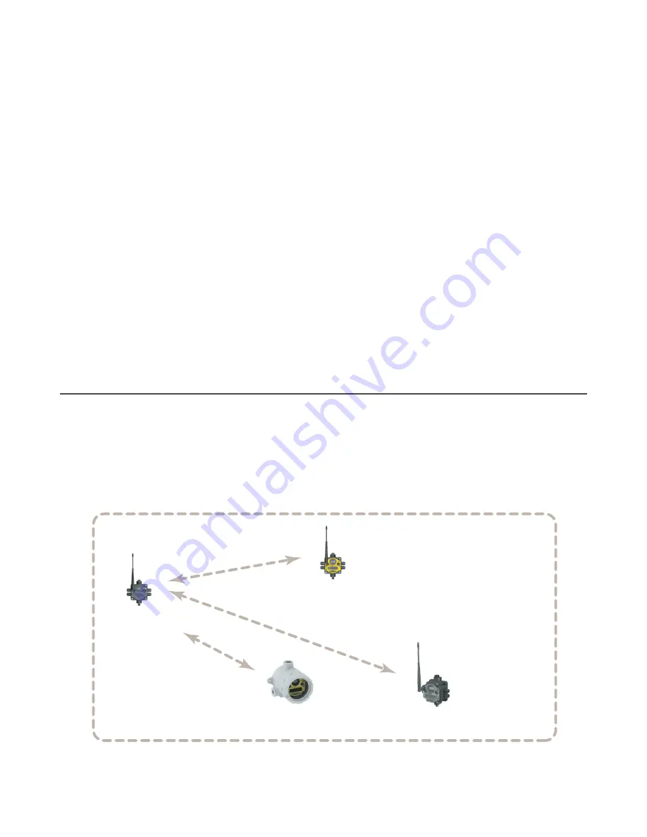
3.1 Mixing Performance and Non-Performance (150 mW)
Radios in the Same Network

To comply with federal regulations, the 150 mW radios and 1 Watt radios communicate differently. All Performance models

offer the ability to select between 250 mW and 1 Watt operation using the DIP switches. To mix Performance radios with

non-Performance radios:

• Operate Performance radios in 250 mW mode, not 1 Watt mode

• Set non-Performance (150 mW) radios to use Extended Address Mode

The 150 mW, 250 mW, and 1 Watt networks operate when collocated, but verify the antenna separation distance between a

Gateway and Node or between two Gateways are at least 10 feet apart. For more detailed instructions about setting up

your wireless network, refer to the Quick Start Guide (p/n 

128185

).


Sure Cross DX80 Gateway  
(150 mW radio)

Sure Cross DX80 Node 
(150 mW radio)

Sure Cross Performance Node  
(in 250 mW mode)

Sure Cross DX99 Node 
(150 mW radio)

Up to 3 miles


Sure Cross

®

 Performance DX80 Wireless I/O Networks


www.bannerengineering.com - Tel: + 1 888 373 6767

13

Содержание Sure Cross DX80 Series

Страница 1: ...Sure Cross Performance DX80 Wireless I O Networks Instruction Manual Original Instructions 132607 Rev O 13 March 2019 Banner Engineering Corp All rights reserved 132607...

Страница 2: ...urvey Results 19 3 6 5 Improving Your Site Survey Results 20 4 Installing Your Sure Cross Radios 22 4 1 Mounting SureCross Devices Outdoors 22 4 1 1 Watertight Glands and NPT Ports 22 4 2 Other Instal...

Страница 3: ...DX80 Performance Documentation 48 6 2 Troubleshooting 48 6 2 1 Startup Problems 48 6 2 2 LED Message Codes 49 6 2 3 LCD Message Codes 50 6 2 4 Inputs and Outputs 51 6 2 5 Radio Link Time Out and Recov...

Страница 4: ...rk and the host controller When the Gateway using its Modbus RTU RS 485 connection is a Modbus slave to a Modbus RTU host controller the wireless network may contain up to 47 Nodes in a single wireles...

Страница 5: ...0 wireless network configuration Modbus RTU master Modbus TCP client server Script Basic e mail data logging and trending Gateway Power DX83 Ethernet Bridge Ethernet cable crossover cable when connect...

Страница 6: ...gs DX81P6 Six pack battery supply module BWA SOLAR PANEL 3W BWA SOLAR PANEL 5W or BWA SOLAR PANEL 20W Includes 3 W 5 W or 20 W solar panel Order the solar controller model BWA Solar CNTRL 12V separate...

Страница 7: ...also used to wake integrated battery models from the hibernation mode they ship in 4 Push button 2 Double click to select a menu and to enter manual scrolling mode Double click to move up one level at...

Страница 8: ...ouble click to select a menu and to enter manual scrolling mode Double click to move up one level at a time 5 LED 1 and 2 Provide real time feedback to the user regarding RF link status serial communi...

Страница 9: ...Node by connecting the 10 to 30 V dc cable or the DX81 Battery Supply Module as shown To apply power to a FlexPower Node with an integrated battery install the battery into the housing The Node start...

Страница 10: ...0 2 56 65 0 2 56 80 3 3 16 80 8 3 18 60 2 36 120 4 72 127 5 19 0 75 30 65 1 21 22 2 0 875 7 9 0 31 7 65 0 30 14 67 0 578 DX80 C Gateways and Nodes 7 9 0 31 80 8 3 18 65 0 2 56 80 3 3 16 65 0 2 56 7 65...

Страница 11: ...45 13 7 mm 0 54 36 2 mm 1 42 148 1 mm 5 83 55 9 mm 2 20 2X Dia 8 3 mm 0 33 Figure 1 DX80 E Housing 2 6 2 GatewayPro 65 0 2 56 65 0 2 56 80 3 3 16 80 8 3 18 136 5 35 7 9 0 31 7 65 0 30 60 2 36 14 67 0...

Страница 12: ...0 578 2 6 4 DX80 E Housings 6 mm 0 24 3 2 mm 0 13 167 4 mm 6 59 75 3 mm 2 96 2X 12 14 NPSM 20 1 mm 0 79 87 6 mm 3 45 13 7 mm 0 54 36 2 mm 1 42 148 1 mm 5 83 55 9 mm 2 20 2X Dia 8 3 mm 0 33 Figure 2 DX...

Страница 13: ...lid green and the Node s LED flashes green to indicate it is communicating with the Gateway 6 Configure any I O points to use the sensors connected to the Sure Cross devices 7 Conduct a site survey be...

Страница 14: ...nnecting the 10 to 30 V dc cable as shown The Gateway begins in RUN mode displays the current network ID NID then identifies itself as a Gateway 2 Apply power to the Node by connecting the 10 to 30 V...

Страница 15: ...een LED flashes alternately while the Node searches for the Gateway After binding is complete the LED is red and green for four seconds looks amber then the red and green flash simultaneously looks am...

Страница 16: ...e radio signal strength of received data packets and reporting the number of missed packets that required a retry Perform a Site Survey before permanently installing the radio network to ensure reliab...

Страница 17: ...adjust right rotary switch to survey the selected Node Double click Button 2 AUTO DISPLAY LOOP Site Survey Gateway The SITE menu displays the device number of the Node the Site Survey was conducted w...

Страница 18: ...e number 1 through 47 0x01 to 0x2F to the Gateway Modbus holding register for I O 15 Modbus Register 15 8 7 0 I O 15 Control Code Data Field I O 15 Control Messages Control Code Data Field Restriction...

Страница 19: ...iring a retry Judging if the reliability of a network s signal meets the needs of the application is not just a matter of green yellow and red packets received In normal operating mode when data packe...

Страница 20: ...all number of yellow signals and a small to medium number of missed signals or one to two flashes per second To improve your radio performance consider using one of the 6 dBi or 8 dBi omni directional...

Страница 21: ...meters long BWC 4MNFN30 30 meters long Requires a surge suppression device model BWC LFNBMN DC if the antenna is external to a building connected to other electronics or elevated BWA 9Y10 A 10 dBd YAG...

Страница 22: ...ch NPT port of the SureCross radios 4 1 1 Watertight Glands and NPT Ports To make glands and plugs watertight use PTFE tape and follow these steps 1 Wrap four to eight passes of polytetrafluoroethylen...

Страница 23: ...e or national regulations When Installing 1 Watt Radios Notice This equipment must be professionally installed The output power must be limited through the use of firmware or a hardware attenuator whe...

Страница 24: ...ackets for a given link is better However seasonal changes may affect the signal strength and the total signal quality Radios installed outside with 50 missed packets in the winter months may have 80...

Страница 25: ...ct the DX80 unit from transients noise and ground plane interference originating from devices or the environment Contact Banner Engineering Corp for more information 4 4 1 Weatherproof Remote Antenna...

Страница 26: ...derstorm 4 4 3 Mount a Dome Antenna to the Enclosure Use a D dome antenna when mounting an antenna directly to the outside of the enclosure 1 3 2 1 Dome antenna 2 DIN rail and DIN rail bracket 3 Enclo...

Страница 27: ...pe Female Connection BWA 9Y6 A 6 5 dBd 6 8 13 inches Outdoor 900 MHz Datasheet b_3145127 BWA 9Y10 A 10 dBd 6 8 24 inches Outdoor 900 MHz Datasheet b_3145130 Omni Directional Fiberglass Antennas with N...

Страница 28: ...RP SMA to RP SMA BWC LFNBMN DC Surge Suppressor bulkhead N Type dc Blocking N Type Female N Type Male Use the RP SMA to N Type male cables to connect the radio to the surge suppressor RP SMA to N Typ...

Страница 29: ...otary switch to survey the selected Node Single click Button 2 Double click Button 2 Double click Button 2 NOD XX EC XX CLEAR ERR ERASED ERR DISABL ERROR DISABL IGNORE Next Device Single click Button...

Страница 30: ...twork ID DINFO RUN FCTRY DVCFG DERR AUTO DISPLAY LOOP AUTO DISPLAY LOOP AUTO DISPLAY LOOP DEV NOD XX NAME NODE XX KIT XXXXX NID XX DEV NOD XX RADIO MICRO V 00 0 A DX80 S N 0x0000 2 LCD MICRO 0x0000 2...

Страница 31: ...Single click Button 1 0 00 Gateway Node On the Gateway the I O displayed may be the I O of the Gateway or of a selected Node To view the I O of a specific Node set the position of the rotary dials to...

Страница 32: ...ce name the network ID NID slave ID baud rate and parity When in extended address mode the DINFO menu also displays the maximum Node setting and the extended addressing XADR or binding code used to fo...

Страница 33: ...RO V 00 0 A DX80 S N 0000 DX80 MODEL 0000 00 PROD DATE 00 00 Single click Button 1 Factory Info FCTRY AUTO DISPLAY LOOP DEV NOD XX RADIO MICRO V 00 0 A DX80 S N 0x0000 2 LCD MICRO 0x0000 2 PROD DATE 0...

Страница 34: ...SITE menu displays the device number of the Node the Site Survey was conducted with as well as the missed green yellow and red received packet count The SITE menu is only available on the Gateways To...

Страница 35: ...r baud rate are 19200 38400 or 9600 For parity select None Even or Odd Extended Address Binding Code Binding Nodes to a Gateway ensures the Nodes only exchange data with the Gateway they are bound to...

Страница 36: ...on 2 PRIOR NADR XX NEW NADR XX CONFRM NADR XX Single click Button 1 to advance through menu Node 5 1 6 DERR Device Error Menu Use the DERR menu to manage device error messages DERR Single click Button...

Страница 37: ...from a GatewayPro or from a DX83 Ethernet Bridge serially connected to the Gateway The Ethernet Bridge and GatewayPro each ship with an Ethernet crossover cable One end of the cable is a RJ45 connecto...

Страница 38: ...lems connecting verify the browser is not set to use a proxy server Use a crossover Ethernet cable when connecting directly from a host computer to the DX83 Ethernet Bridge or GatewayPro use a standar...

Страница 39: ...range that are also in binding mode The extended addressing binding code defines the network and all radios within a network must use the same code After binding your Nodes to the Gateway make note o...

Страница 40: ...e Node s rotary dials to assign a decimal Node address between 01 and 47 The left rotary dial represents the tens digit 0 4 and the right dial represents the ones digit 0 9 of the device address 16 Re...

Страница 41: ...splays DVCFG 2 Single click button 2 to enter the DVCFG menu options and stop at NID The Gateway s LCD displays NID 3 Single click button 2 Enters the NID menu option 4 Using both rotary dials on the...

Страница 42: ...or another Node in the network Follow the submenu structure to the XADR display for that device 1 Apply power to the Node 5 The LCD displays POWER then RUN 2 On the Node single click button 1 to advan...

Страница 43: ...minute before waking it Sleep Mode applies to both battery and 10 30 V dc powered models During normal operation the Sure Cross radio devices enter sleep mode after 15 minutes of operation The radio...

Страница 44: ...o select the digit the digit changes to reflect the position of the right rotary dial To set the slave ID to 3 the display should read 003 6 Press button 2 once to save your current setting The displa...

Страница 45: ...If the Gateway and Nodes lose their connection the network may take up to 20 seconds to re synchronize 7 Double click Gateway push button 2 to return to the Device Configuration DVCFG menu 8 Click Gat...

Страница 46: ...are set to the user defined default state Each Node has a Gateway Link Failure flag that can be set or cleared depending on the particular application Host System Gateway Node 1 Node 2 In the sample s...

Страница 47: ...n Max Min Max Discrete 0 1 0 1 0 to 20 mA 0 0 mA 20 0 mA 0 65535 20 mA 65535 Reg Value mA Linear mapping of unsigned register value to current 4 to 20 mA 4 0 mA 20 0 mA 0 65535 16 mA 65535 Reg Value 4...

Страница 48: ...an integrated battery ship from the factory in storage mode to conserve the battery To wake the device press and hold button 1 for 5 seconds To put any FlexPower or integrated battery Sure Cross radi...

Страница 49: ...y is less than two meters from another Gateway send and receive transmissions between all devices the Gateways communicate with fails 2 The Gateway and Node may be too far apart to achieve synchroniza...

Страница 50: ...to 30 V dc After replacing the battery allow up to sixty seconds for the device to power up Modbus Message Codes for Register 8 Register I O 8 is reserved for device messages or Site Survey data when...

Страница 51: ...e is in sync with its Gateway 6 2 5 Radio Link Time Out and Recovery Non Host Connected Systems The SureCross wireless devices employ a deterministic link time out method to address radio link interru...

Страница 52: ...g the Rotary Dial Access Cover Check the rotary dial access cover o ring every time the access cover is removed Replace the o ring when it is damaged discolored or showing signs of wear The o ring sho...

Страница 53: ...er Engineering WARNING Potential electrostatic charging hazard only clean with a damp cloth The replacement battery MUST be a Banner approved battery model number BWA BATT 001 Use of a different batte...

Страница 54: ...d set aside the radio and spacer frame 4 If you are replacing an existing battery remove the discharged battery 5 Insert a new battery Only use a 3 6 V lithium battery from Xeno model number XL 205F 6...

Страница 55: ...ay cause harmful interference to radio communications However there is no guarantee that interference will not occur in a particular installation If this equipment does cause harmful interference to r...

Страница 56: ...and or Consult the dealer or an experienced radio TV technician for help Antenna Warning This device has been tested with Reverse Polarity SMA connectors with the antennas listed in Table 3 on page 5...

Страница 57: ...de displayed under the DVCFG XADR menu on the Gateway s LCD Knowing the binding code prevents having to re bind all Nodes if the Gateway is ever replaced binding MultiHop networks Binding MultiHop rad...

Страница 58: ...down a conveyor counter frequency The frequency counter calculates the frequency of the input signal in Hz Frequency counters can be used to measure flow rates such as measuring the flow rate of items...

Страница 59: ...s are set to the user defined states and the inputs are frozen Gateway Link Failure Gateway link failures are determined by three global parameters Polling Interval Maximum Missed Message Count and Re...

Страница 60: ...t for any discrete output or switch power output FlexPower Banner s FlexPower technology allows for a true wireless solution by allowing the device to operate using either 10 to 30 V dc 3 6 V lithium...

Страница 61: ...ions Using the Nodes to notify the Gateway that the radio link is active instead of having the Gateway poll the Nodes saves energy and increases battery life I am here hibernation storage mode While i...

Страница 62: ...e with the Gateway and the Node Link Failure flag is selected the output points are set to the user defined states and the inputs are frozen local and non local registers Local registers are registers...

Страница 63: ...directions out of sync link loss loss of radio signal The Sure Cross wireless devices use a deterministic link time out method to address RF link interruption or failure When a radio link fails all pe...

Страница 64: ...ature measurement device that measures the electrical resistance across a pure metal The most commonly used metal is platinum because of its temperature range accuracy and stability RTDs are used for...

Страница 65: ...ng the number of missed packets that required a retry slave ID The slave ID is an identifying number used for devices within a Modbus system By default Gateways are set to Modbus Slave ID 1 When using...

Страница 66: ...ssing of information time division multiple access TDMA TDMA is a wireless network communication architecture that provides a given slot of time for each device on the network providing a guaranteed o...

Страница 67: ...th a transmitter and receiver in one housing and shares circuitry abbreviated as RxTx wireless sensor network WSN A wireless sensor network is a network of low power electronic devices that combine se...

Страница 68: ...any product of its manufacture which at the time it is returned to the factory is found to have been defective during the warranty period This warranty does not cover damage or liability for misuse ab...

Страница 69: ...ale 47 G gasket main body 52 ground 23 ground wire 24 27 I I O isolation 24 27 input value 47 L lightning arrestor 24 27 link time out 51 M mechanical stress 23 Modbus communication parameters 44 45 M...

Отзывы: