Contact Banner Engineering for additional information about connecting other devices not described in this manual.
3.4.2
XS/SC26-2
Safety Outputs
The Safety Outputs are designed to control Final Switching Devices (FSDs) and Machine Primary Control Elements (MPCEs)
that are the last elements (in time) to control the dangerous motion. These control elements include relays, contactors,
solenoid valves, motor controls, and other devices that typically incorporate force-guided (mechanically-linked) monitoring
contacts, or electrical signals needed for external device monitoring.
The Safety Controller has two independently controlled and redundant solid-state Safety Outputs (terminals SO1a & SO1b,
and SO2a & SO2b). The Safety Controller’s self-checking algorithm ensures that the outputs turn On and Off at the
appropriate times, in response to the assigned input signals.
Each redundant solid-state Safety Output is designed to work either in pairs or as two individual outputs. When controlled
in pairs, the Safety Outputs are suitable for Category 4 applications; when acting independently, they are suitable for
applications up to Category 3 when appropriate fault exclusion has been employed (see
Single-channel Control
Safety Circuit Integrity and ISO 13849-1 Safety Circuit Principles
on page 26).
on page 46 for more information about hookup, solid-state and safety relay outputs, external device
monitoring, single/dual-channel Safety Stop Circuits, and configuring Safety Outputs.
Additional solid-state or safety relay outputs can be added to expandable models (XS26-2xx) of the Base Controller by
incorporating expansion output modules (XS2so, XS4so, XS1ro, and XS2ro). Up to eight expansion modules, in any
combination of input or output modules, can be added.
The Safety Outputs can be controlled by input devices with both automatic and manual reset operation.
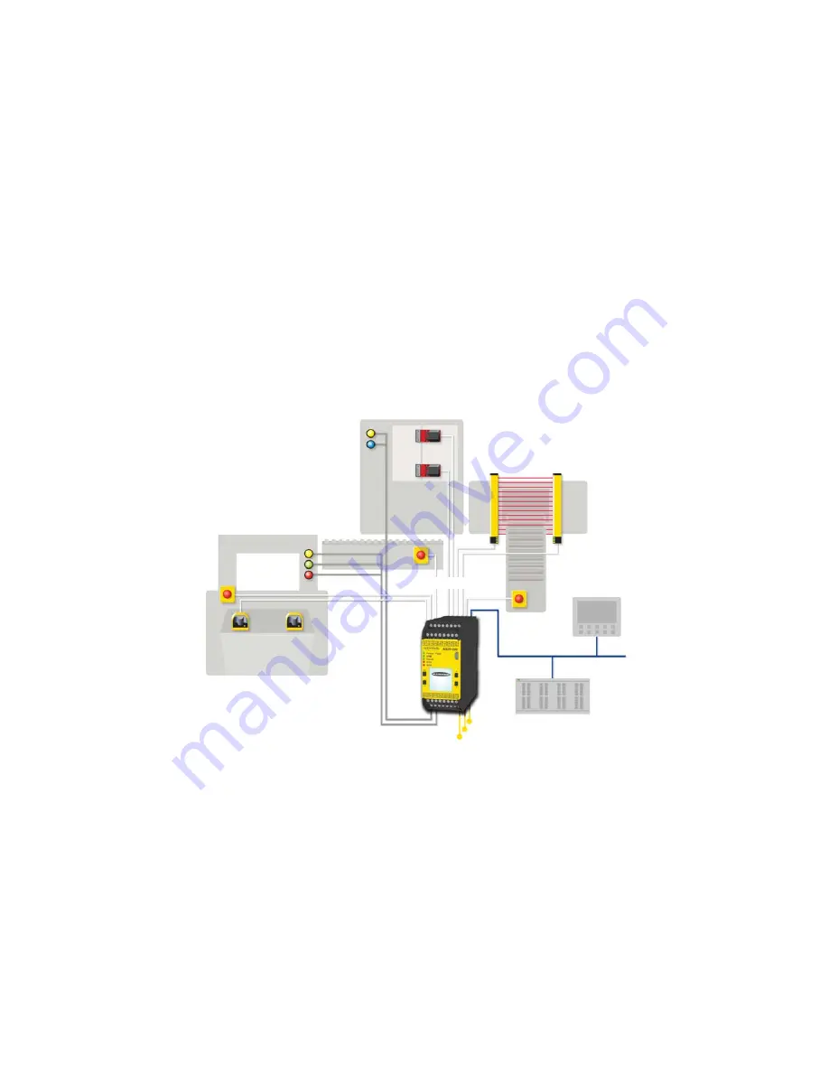
Safety Outputs
Status Outputs
Ethernet
PLC
HMI
Safety Input Devices
Figure 2. Safety Outputs (Example Application)
Functional Stops according to IEC 60204-1 and ANSI NFPA79
The Safety Controller is capable of performing two functional stop types:
• Category 0: an uncontrolled stop with the immediate removal of power from the guarded machine
• Category 1: a controlled stop with a delay before power is removed from the guarded machine
Delayed stops can be used in applications where machines need power for a braking mechanism to stop the hazardous
motion.
3.4.3
XS/SC26-2
Status Outputs and Virtual Status Outputs
The Base Controller has eight convertible I/Os (labeled IOx) that can be used as Status Outputs which have the capability to
send non-safety status signals to devices such as programmable logic controllers (PLCs) or indicator lights. In addition, any
unused Safety Output terminals may be configured to perform a Status Output function with the benefit of higher current
on page 16 for more information). For the solid state safety outputs configured as
XS/SC26-2 and SC10-2 Safety Controllers
10
www.bannerengineering.com - Tel: + 1 888 373 6767


