


Protective Stop (Safety Stop) Circuits
A protective stop (safety stop) allows for an orderly cessation of motion for safeguarding purposes, which results in a stop of
motion and removal of power from the MPCEs (assuming this does not create additional hazards).
A protective stop circuit typically comprises a minimum of two normally open contacts from forced-guided, mechanically
linked relays, which are monitored through External Device Monitoring (EDM) to detect certain failures to prevent the loss of
the safety function. Such a circuit can be described as a "safe switching point". Typically, protective stop circuits are either
single-channel, which is a series connection of at least two normally open contacts; or dual-channel, which is a separate
connection of two normally open contacts. In either method, the safety function relies on the use of redundant contacts to
control a single hazard. If one contact fails On, the second contact arrests the hazards and prevents the next cycle from
occurring. See
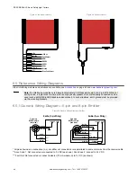
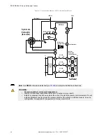
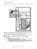
Generic Wiring Diagram—8-pin Receiver and Redundant FSDs
The interfacing of the protective stop circuits must be accomplished so that the safety function cannot be suspended,
overridden, or defeated, unless accomplished in a manner of the same or greater degree of safety as the machine’s safety
related control system that includes the EZ-SCREEN LS Basic.
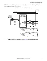
The normally open safety outputs from an interface module provide a series connection of redundant contacts that form
protective stop circuits for use in either single-channel or dual-channel control. See
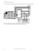
Generic Wiring Diagram—8-pin Receiver
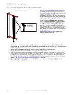
Dual-Channel Control
Dual-channel control provides the ability to electrically extend the safe switching point beyond the FSD contacts.
With proper monitoring, this method of interfacing is capable of detecting certain failures in the control wiring between the
safety stop circuit and the MPCEs. These failures include a short-circuit of one channel to a secondary source of energy or
voltage, or a loss of the switching ability of one of the FSD outputs. Such failures may lead to a loss of redundancy, or to a
complete loss of safety, if not detected and corrected.
The possibility of a failure to the wiring increases as the physical distance between the FSD safety stop circuits and the
MPCEs increases, as the length or the routing of the interconnecting wires increases, or if the FSD safety stop circuits and
the MPCEs are located in different enclosures. For this reason, dual-channel control with EDM monitoring should be used in
any installation where the FSDs are located remotely from the MPCEs.
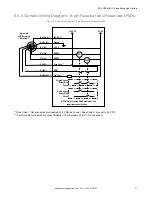
Single-Channel Control
Single-channel control uses a series connection of FSD contacts to form a safe switching point.
After this point in the machine’s safety-related control system, failures can occur that would result in a loss of the safety
function (such as a short-circuit to a secondary source of energy or voltage). For this reason, single-channel control
interfacing should be used only in installations where FSD safety stop circuits and the MPCEs are mounted within the same
control panel, adjacent to each other, and are directly connected to each other; or where the possibility of such a failure can
be excluded. If this cannot be achieved, then dual-channel control should be used.
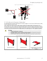
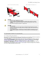
Methods to exclude the possibility of these failures include, but are not limited to:
•
Physically separating interconnecting control wires from each other and from secondary sources of power
•
Routing interconnecting control wires in separate conduit, runs, or channels
•
Locating all elements (modules, switches, and devices under control) within one control panel, adjacent to each
other, and directly connected with short wires
•
Properly installing multi-conductor cabling and multiple wires through strain relief fittings. Over-tightening of a strain-
relief can cause short-circuits at that point.
•
Using positive-opening or direct-drive components, installed and mounted in a positive mode
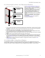
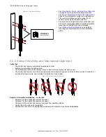
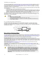
6.4.3 Machine Primary Control Elements and EDM Input
A machine primary control element (MPCE) is an electrically powered element that directly controls the normal operation of a
machine in such a way that it is the last element (in time) to function when machine operation is to be initiated or arrested
(per IEC 61496-1). Examples include motor contactors, clutch/brakes, valves, and solenoids.
Depending on the level of risk of harm, it may be required to provide redundant MPCEs or other control devices that are
capable of immediately stopping the dangerous machine motion, irrespective of the state of the other. These two machine
control channels need not be identical (diverse redundant), but the stop time performance of the machine (Ts, used to
calculate the safety distance, see
Calculating the Safety Distance (Minimum Distance)
on page 21) must take into account
the slower of the two channels. Consult the machine manufacturer for additional information.
To ensure that an accumulation of failures does not compromise the redundant control scheme (cause a failure to danger), a
method to verify the normal functioning of MPCEs or other control devices is required. EZ-SCREEN LS Basic provides a
convenient method for this verification: external device monitoring (EDM).
For the EZ-SCREEN LS Basic external device monitoring to function properly, each device must include a normally closed,
forced-guided (mechanically linked) contact that can accurately reflect the status of the device. This ensures that the
normally open contacts, used for controlling hazardous motion, have a positive relationship with the normally closed
monitoring contacts and can detect a failure to danger (for example, contacts that are welded closed or stuck On).
EZ-SCREEN
®
LS Basic Safety Light Curtain
www.bannerengineering.com - Tel: + 1 888 373 6767
43