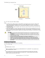
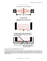
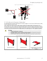

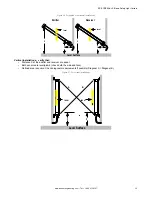

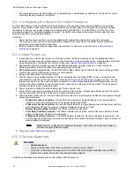

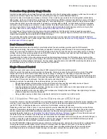

Figure 17. Examples of Incorrect Emitter/Receiver Orientation
Receiver
Emitter
Receiver
Emitter
Cable ends point in opposite directions
Problem:
Voids in defined area
Emitter and receiver not parallel to each other
Problem:
Reduced excess gain
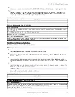
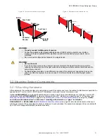
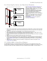
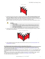
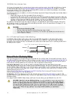
5.1.9 Installation of Multiple Systems
Whenever two or more EZ-SCREEN LS Basic emitter and receiver pairs are adjacent to one another, optical crosstalk may
take place between the systems. To minimize optical crosstalk, alternate the positions of the emitters and receivers or
alternate Scan Codes.
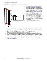
When three or more systems are installed in the same plane (as shown), optical crosstalk may occur between sensor pairs
whose emitter and receiver lenses are oriented in the same direction. In this situation, eliminate optical crosstalk by mounting
these sensor pairs exactly in line with each other within one plane or by adding a mechanical barrier between the pairs.
To further aid in avoiding crosstalk, the sensors feature two selectable scan codes. A receiver set to one scan code will not
respond to an emitter set to another code.
Figure 18. Two systems installed in a horizontal plane
Receiver
Emitter
Scan Code 2
Receiver
Emitter
Scan Code 1
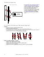
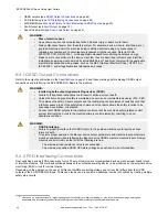
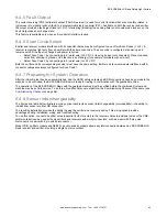
Figure 19. Two or three systems stacked (or alternate receiver/emitter
positions)
Receiver
Emitter
Scan Code 2
Receiver
Emitter
Scan Code 1
EZ-SCREEN
®
LS Basic Safety Light Curtain
30
www.bannerengineering.com - Tel: + 1 888 373 6767