


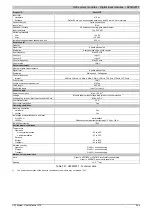


X20 system modules • Digital input modules • X20DI2377
X20 system User's Manual 3.10
951
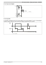
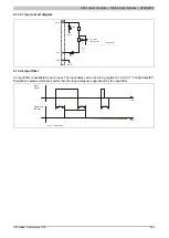
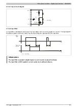
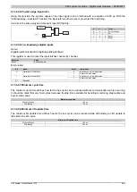
4.13.4.7 Input circuit diagram
Input x
GND
GND
GND
VDR
I/O status
LED (green)
Input status
24 V
24 V
PTC
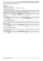
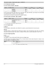
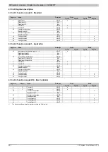
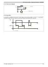
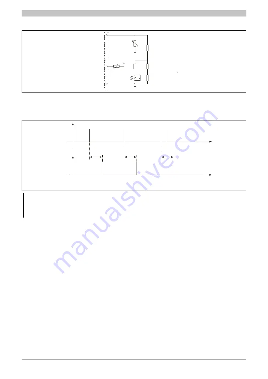
4.13.4.8 Input filter
An input filter is available for each input. The input delay can be set using register 4.13.4.9.4.1 "ConfigOutput01".
Disturbance pulses which are shorter than the input delay are suppressed by the input filter.
Input
signal
Signal after
the filter
t
Delay
t
Delay
t
Delay
t
Delay
Time
Time
⇒ Input delay
Information:
The input filter is applied to digital inputs in event counter mode with software
The input filter is NOT applied in event counter mode without software.


