BIS Z-GW-001-PBS
Subnet16™ Profibus Gateway
INSTALLATION GUIDE
This document provides instructions and information designed
to assist users in the hardware setup of the Subnet16™
Profibus Gateway. For configuration details see the Gateway
Series Reference Manual.
The BIS Z-GW-001-PBS is designed to connect RFID
applications to a Profibus network. The Gateway is a Profibus
Slave node which connects to a Profibus Master (Host PC or
PLC) through a Profibus-compatible network cable.
It supports Subnet16™ Multidrop bus architecture, a
subnetwork of up to sixteen Processor stations, through an
RS485 interface connection.
A USB port is used for establishing a direct serial connection
with a host computer for the purpose of configuring the
Gateway through the Dashboard Configuration Tool program.
TECHNICAL DATA
ELECTRICAL FEATURES
Power Supply
12 - 30 Vdc
DC Input Current max.
200 mA - 100 mA
Communication Interfaces:
Host
RFID Multidrop Readers
Configuration
Profibus
Subnet16™
(uses RS485 physical layer)
USB 2.0
Baud Rate
9600 (default) to 115200
ENVIRONMENTAL FEATURES
Operating Temperature
-20° to +50 °C
(-4° to +122 °F)
Storage Temperature
-20° to +70 °C
(-4° to +158 °F)
Humidity max.
90% non condensing
Vibration Resistance
EN 60068-2-6
14 mm @ 2 to 10 Hz;
1.5 mm @ 13 to 55 Hz;
2 g @ 70 to 200 Hz;
2 hours on each axis
Shock Resistance
EN 60068-2-27
30 g; 11 ms;
3 shocks on each axis
Protection Class
EN 60529
IP30
PHYSICAL FEATURES
Dimensions
104 x 107 x 32 mm
(4.1 x 4.2 x 1.3 in)
Weight
256 g (9 oz)
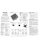
USER INTERFACE
LED Indicators
Power On, Subnet16™ Bus,
Profibus Status, Profibus
Mode, Configuration Error
GENERAL VIEW
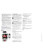
LED INDICATORS
green
POWER
The POWER LED is ON whenever
power is applied to the Gateway.
amber
Subnet16™
BUS
The BUS LED will flash ON and OFF to
indicate that data is being transmitted
between the Gateway and one or more
RFID processors on the Subnet16™
network.
green/red
PROFIBUS
MODE
SOLID GREEN: on-line, data exchange
FLASHING GREEN: on-line, but idle.
FLASHING RED (1 FLASH):
parametrization error
FLASHING RED (2 FLASHES):
Profibus configuration error
green/red
PROFIBUS
STATUS
SOLID GREEN: initialized.
FLASHING GREEN: initialized,
diagnostic event(s) present.
SOLID RED: exception error
red
ERROR
The Error LED is solid red when a
Gateway
configuration
error
has
occurred, i.e. an invalid or unrecognized
command. This LED will be cleared
when a valid command is sent.
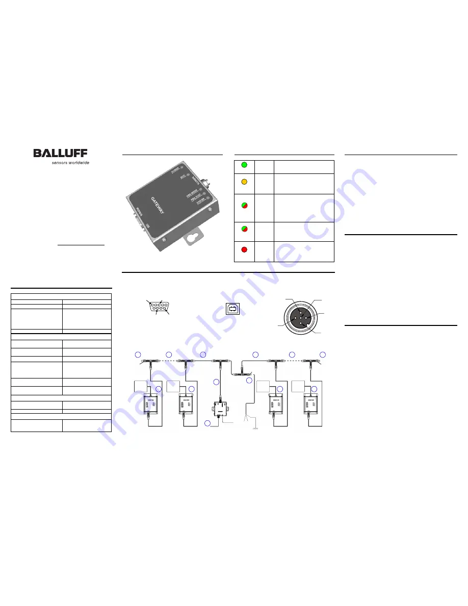
CONNECTIVITY
Profibus
D-sub 9-pin Female Connector (Data and
Bus Termination Power)
USB Configuration
USB Type B Female Connector
1
2
3
4
Subnet16™
M12 5-pin Female Connector (Data
and Power Supply)
Typical Layout
See the Gateway Series Reference Manual for a complete list of accessories including alternative cables and connectors.
HARDWARE REQUIREMENTS
The following components are required for a complete Subnet16™
RFID system:
•
One Subnet16™ Profibus Gateway Interface Module
•
One Profibus-capable host; Programmable Logic Processor
(PLC) or PC
•
One to 16 processors (BIS M-41x, BIS M-62x or BIS U-62x-
Series Processors - RS485 models)
•
Adequate length cabling, connectors and terminators
•
A suitable power supply capable of providing sufficient power
to the Gateway and its Processor’s via Subnet16™ network
cabling
•
Balluff RFID data carrier or labels: BIS M-1xx or BIS U-1xx
INSTALLATION GUIDELINES
•
Do not route cables near unshielded cables or near wiring carrying
high voltage or high current. Cross cables at perpendicular
intersections and avoid routing cables near motors and solenoids.
•
Review the power requirements of your RFID network and provide
a suitable power supply.
•
Avoid mounting the processor near sources of EMI (electro-
magnetic interference) or near devices that generate high ESD
(electro-static discharge) levels. Always use adequate ESD
prevention measures to dissipate potentially high voltages.
•
If electrical interference is encountered (as indicated by a
significant reduction in read/write performance), relocate the
processor to an area free from potential sources of interference.
•
Perform a test phase by constructing a small scale, independent
network that includes only the essential devices required to test
your RFID application (use Balluff approved Subnet16™ cables
and accessories).
INSTALLATION
The numbered steps in the following procedure are also indicated in
the Subnet16™ network example layout shown in the figure.
1. Preliminary Notes: Read this document in its entirety and note
the Installation Guidelines above.
2. Mounting: Mount the Gateway to your chosen location using two
M5 (#10) screws, lock washers and nuts. The Gateway may be
mounted in any orientation, but should be aligned in such a
manner that the LED indicators can be seen during operation.
3. Gateway Connection: Attach one end of a 5-pin, male-to-male,
M12, ThinNet drop cable (P/N: BCC0ET4) to the 5-pin, female,
M12 connector on the Gateway. Connect the other end of this 5-
pin, male-to-male, M12, ThinNet drop cable to the 5-pin, female,
M12 connector on a ThinNet to ThinNet Drop-T Connector (as
per your network and RFID application requirements).
4. Trunk Wiring: Attach one end of a male-to-female trunk cable to
each mating connector on the Drop-T Connector. Continue
connecting trunk cables and Drop-T connectors as needed.
Note: trunk length should not exceed 300 m for ThickNet and 20 m
for ThinNet.
5. Termination Resistors: For ThinNet Networks: Connect a
Terminating Resistor (P/N: BCC9MR, male) to the first and last
Drop-T Connector on the trunk line.
(over)
PIN 5:
TX/RX-
PIN 1:
SIGNAL
GND
PIN 4:
TX/RX+
PIN 3:
GND
PIN 2:
VDC
VDC
GND
D-
D+
PIN 4:
RTS
PIN 8:
A Line (-)
PIN 5:
GND
PIN 6:
+5 VDC
PIN 3:
B Line (+)
BCC07WR
BCC0E04
B
C
C
0
7
W
R
BCC0E04
BCC0E04
BCC0E04
B
C
C
0
9
M
R
B
C
C
0
E
0
4
G
a
te
w
a
y
to Profibus
Master (Host)
to Power Supply
Vdc GND
B
C
C
0
9
M
R
BCC06ZF
BIS U-30X
B
IS
U
-6
2
0
-0
6
7
-1
X
1
-0
4
-S
9
2
BIS U-30X
BIS U-30X
BIS U-30X
BCC07WR
BCC07WR
BCC07WR
BCC07WR
B
C
C
0
E
T
4
B
C
C
0
E
0
4
B
C
C
0
E
0
4
B
C
C
0
E
0
4
B
C
C
0
E
0
4
B
IS
U
-6
2
0
-0
6
7
-1
X
1
-0
4
-S
9
2
B
IS
U
-6
2
0
-0
6
7
-1
X
1
-0
4
-S
9
2
B
IS
U
-6
2
0
-0
6
7
-1
X
1
-0
4
-S
9
2
4
3
4
4
4
5
5
6
6
6
6
8
7