background image

BTL5-T1 _ _ -M _ _ _ _ -P-S103

 deutsch 

Betriebsanleitung

 english 

User’s guide


français 

Notice d’utilisation


italiano 

Manuale d’uso


español 

Manual de instrucciones

Содержание BTL5-T1**-M****-P-S103 series

Страница 1: ...BTL5 T1_ _ M_ _ _ _ P S103 deutsch Betriebsanleitung english User s guide fran ais Notice d utilisation italiano Manuale d uso espa ol Manual de instrucciones...

Страница 2: ...www balluff com...

Страница 3: ...Betriebsanleitung deutsch BTL5 T1_ _ M_ _ _ _ P S103...

Страница 4: ...www balluff com...

Страница 5: ...Anschluss 8 4 1 BTL einbauen 8 4 2 Gef hrte Positionsgeber 8 4 3 Freie Positionsgeber 9 4 4 Schirmung und Kabelverlegung 10 4 5 Elektrischer Anschluss 11 4 5 1 Anschluss der Versorgungsspannung der St...

Страница 6: ...3 Freie Positionsgeber 16 7 4 Steckverbinder und Kabel 17 7 4 1 Steckverbinder frei konfektionierbar 17 7 4 2 Steckverbinder konfektioniert 17 7 4 3 Verbindungskabel konfektioniert 18 7 4 4 Busabschlu...

Страница 7: ...re GSD Datei per Download im Internet unter www balluff com oder per E Mail bei service balluff de 1 5 Zulassungen und Kennzeichnungen UL Zulassung File No E227256 US Patent 5 923 164 Das US Patent wu...

Страница 8: ...nete Sicherheitsma nahmen treffen kann Der Betreiber hat die Verantwortung dass die rtlich geltenden Sicherheitsvorschriften eingehalten werden Insbesondere muss der Betreiber Ma nahmen treffen dass b...

Страница 9: ...t werden Der Mindestabstand L zwischen den Positionsgebern muss 65 mm betragen Bild 3 2 L L L Abstand zwischen den Positionsgebern 3 1 Aufbau Elektrischer Anschluss Der elektrische Anschluss ist ber e...

Страница 10: ...f hren 2 BTL mit den Befestigungsschrauben auf dem Unter grund fixieren Schrauben in den Klammern mit max 2 Nm festziehen 3 Postionsgeber Zubeh r einbauen Bei Verwendung mehrerer Positionsgeber Kapite...

Страница 11: ...z C BTL5 P 3800 2 0 1 4 mm 2 mm BTL5 P 5500 2 5 15 mm 15 mm BTL5 P 4500 1 0 1 2 mm 2 mm BTL6 A 3800 2 4 8 mm2 5 mm BTL6 A 3801 2 4 8 mm2 5 mm 1 Der gew hlte Abstand muss ber die gesamte Messl nge kons...

Страница 12: ...ngen durch Netzoberwellen z B von Phasenanschnittsteuerungen f r die der Kabelschirm nur geringen Schutz bietet ber die Profibus DP Schnittstelle wird das Signal zur Steuerung bertragen Kabel paarweis...

Страница 13: ...TxD P B 5 Schirm Tab 4 4 Anschlussbelegung Steuer und Datensignale Pin Versorgungsspannung extern Power 1 24 V 3 0 V GND 4 Schirm Tab 4 5 Anschlussbelegung Versorgungsspannung 4 5 2 Anschlussbeispiel...

Страница 14: ...tands 5 Inbetriebnahme 5 1 System in Betrieb nehmen GEFAHR Unkontrollierte Systembewegungen Bei der Inbetriebnahme und wenn das Positionsmess system Teil eines Regelsystems ist dessen Parameter noch n...

Страница 15: ...IP67 muss der in Bild 4 10 auf Seite 11 vorgeschla gene Busabschlusswiderstand verwendet werden Dann darf die interne Busterminierung nicht aktiviert sein S1 9 und S1 10 auf OFF Nach M glichkeit Stic...

Страница 16: ...lligkeit 0 5 Vss Stromaufnahme bei 24 V DC 7 130 mA Einschaltspitzenstrom 3 A Verpolungsschutz ja berspannungsschutz Transzorb Schutzdioden Spannungsfestigkeit GND gegen Geh use 500 V DC 6 4 Steuersig...

Страница 17: ...24 40 Bild 7 2 Einbauma e Positionsgeber BTL5 F 2814 1S Gewicht ca 28 g Geh use Aluminium Gleitfl che Kunststoff BTL5 T 2814 1S 16 5 11 5 28 22 40 M5x10 Bild 7 3 Einbauma e Positionsgeber BTL5 T 2814...

Страница 18: ...800 2 Gewicht ca 30 g Geh use Kunststoff BTL6 A 3801 2 28 16 21 37 6 4 2 18 13 Bild 7 8 Einbauma e Positionsgeber BTL6 A 3801 2 Gewicht ca 25 g Geh use Kunststoff BTL5 P 4500 1 16 5 45 25 28 15 4 5 25...

Страница 19: ...Steckverbinder gerade frei konfektionierbar M12 5 polig Kabeldurchlass Klemmkorb PG 9 Bild 7 12 62 20 6 8 Steckverbinder BKS S105 00 Stift f r BUS OUT BKS S106 00 Steckverbinder gewinkelt frei konfekt...

Страница 20: ...12 5 polig Unterschiedliche Kabell ngen bestellbar z B BKS S105 CP 05 Kabell nge 5 m Bild 7 17 Verbindungskabel BKS S105 CP 7 4 4 Busabschlusswiderstand frei konfektionierbar BKS S105 R01 Busabschluss...

Страница 21: ...8 V DC Anzahl Positionsgeber 1 1 4 w hlbar ber GSD Nennl nge 4 stellig M0500 metrische Angabe in mm Nennl nge 500 mm M0050 M4000 Bauform P Profilgeh use Elektrischer Anschluss S103 1 x 3 poliger Stift...

Страница 22: ...mrechnungstabelle mm inch 1 inch 25 4 mm inch mm 1 25 4 2 50 8 3 76 2 4 101 6 5 127 6 152 4 7 177 8 8 203 2 9 228 6 10 254 Tab 9 2 Umrechnungstabelle inch mm 9 Anhang 9 2 Typenschild Bild 9 1 Typensch...

Страница 23: ...User s Guide english BTL5 T1_ _ M_ _ _ _ P S103...

Страница 24: ...www balluff com...

Страница 25: ...n and connection 8 4 1 Installing the BTL 8 4 2 Captive magnets 8 4 3 Floating magnets 9 4 4 Shielding and cable routing 10 4 5 Electrical Connection 11 4 5 1 Connecting the supply voltage control and...

Страница 26: ...nt rod 15 7 3 Floating magnets 16 7 4 Connectors and cables 17 7 4 1 Connector freely configurable 17 7 4 2 Connector preassembled 17 7 4 3 Connecting cable preassembled 18 7 4 4 Bus termination resis...

Страница 27: ...nternet at www balluff com or e mail to service balluff de 1 5 Approvals and markings UL approval File No E227256 US Patent 5 923 164 The US patent was awarded in connection with this product The CE M...

Страница 28: ...zards and take appropriate safety measures The operator is responsible for ensuring that local safety regulations are observed In particular the operator must take steps to ensure that a defect in the...

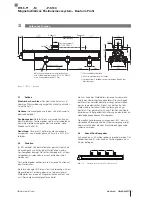
Страница 29: ...a several cables that are connected via connectors 3 3 Number of magnets Up to 4 magnets can be used The distance L between the magnets must be at least 65 mm Fig 3 2 L L L Distance between the magnet...

Страница 30: ...BTL into the mounting clamps 2 Attach the BTL to the base using mounting screws tighten screws in the clamps with max 2 Nm 3 Installing magnet accessory When using multiple magnets see chapter 3 3 Th...

Страница 31: ...mm 2 mm BTL5 P 5500 2 5 15 mm 15 mm BTL5 P 4500 1 0 1 2 mm 2 mm BTL6 A 3800 2 4 8 mm2 5 mm BTL6 A 3801 2 4 8 mm2 5 mm 1 The selected distance must remain constant over the entire stroke length 2 For...

Страница 32: ...e g from phase angle controls are especially critical and the cable shield offers very little protection against this The signal is transmitted to the controller via the Profibus DP interface Cable tw...

Страница 33: ...d Tab 4 4 Control and data signals connection assignment Pin Supply voltage external Power 1 24 V 3 0 V GND 4 Shield Tab 4 5 Supply voltage connection assignment 4 5 2 Connection example Fig 4 10 A B...

Страница 34: ...ncontrolled system movement When starting up if the position measuring system is part of a closed loop system whose parameters have not yet been set the system may perform uncontrolled movements This...

Страница 35: ...Fig 4 10 on page 11 must be used Then the internal bus termination must not be activated S1 9 and S1 10 set to OFF If possible stubs are to be avoided 5 4 3 LED display for Profibus encoder profile LE...

Страница 36: ...0 5 VPP Current draw at 24 V DC 7 130 mA Inrush current 3 A Reverse polarity protection yes Overvoltage protection Transzorb protection diodes Dielectric strength GND to housing 500 V DC 6 4 Control s...

Страница 37: ...7 2 Installation dimensions of BTL5 F 2814 1S magnet Weight Approx 28 g Housing Aluminum Slide surface Plastic BTL5 T 2814 1S 16 5 11 5 28 22 40 M5x10 Fig 7 3 Installation dimensions of BTL5 T 2814 1S...

Страница 38: ...or BTL6 A 3800 2 Weight Approx 30 g Housing Plastic BTL6 A 3801 2 28 16 21 37 6 4 2 18 13 Fig 7 8 Installation dimensions for BTL6 A 3801 2 Weight Approx 25 g Housing Plastic BTL5 P 4500 1 16 5 45 25...

Страница 39: ...105 00 Straight connector freely configurable M12 5 pole Cable feed through pinch ring PG 9 Fig 7 12 62 20 6 8 Connector BKS S105 00 pin for BUS OUT BKS S106 00 Angled connector freely configurable M1...

Страница 40: ...M12 5 pole Various cable lengths can be ordered e g BKS S105 CP 05 Cable length 5 m Fig 7 17 Connecting cable BKS S105 CP 7 4 4 Bus termination resistance freely configurable BKS S105 R01 Bus termina...

Страница 41: ...umber of magnets 1 1 4 can be selected via GSD Nominal length 4 digit M0500 Measurements in mm nominal length 500 mm M0050 M4000 Construction P profile housing Electrical connection S103 1 x 3 pin mal...

Страница 42: ...rsion table mm to inches 1 inch 25 4 mm inch mm 1 25 4 2 50 8 3 76 2 4 101 6 5 127 6 152 4 7 177 8 8 203 2 9 228 6 10 254 Tab 9 2 Conversion table inches to mm 9 Appendix 9 2 Part label Fig 9 1 BTL5 p...

Страница 43: ...Notice d utilisation fran ais BTL5 T1_ _ M_ _ _ _ P S103...

Страница 44: ...www balluff com...

Страница 45: ...BTL 8 4 2 Capteurs de position guid s 8 4 3 Capteurs de position libres 9 4 4 Blindage et pose des c bles 10 4 5 Raccordement lectrique 11 4 5 1 Raccordement des c bles de tension d alimentation de si...

Страница 46: ..._ _ A 15 7 3 Capteurs de position libres 16 7 4 Connecteurs et c bles 17 7 4 1 Connecteurs assembler 17 7 4 2 Connecteur confectionn 17 7 4 3 C ble de connexion confectionn 18 7 4 4 R sistance de ter...

Страница 47: ...ar e mail aupr s de service balluff de 1 5 Homologations et certifications Homologation UL Dossier n E227256 Brevet US 5 923 164 Le brevet am ricain a t attribu en relation avec ce produit Avec le sym...

Страница 48: ...s potentiels et prendre les mesures de s curit ad quates Il est de la responsabilit de l exploitant de veiller ce que les dispositions locales concernant la s curit soient respect es L exploitant doit...

Страница 49: ...ion peuvent tre utilis s La distance minimale L entre les capteurs de position doit tre de 65 mm Fig 3 2 L L L Distance entre les capteurs de position 3 1 Structure Raccordement lectrique le raccordem...

Страница 50: ...e de max 2 Nm dans les brides 3 Monter le capteur de position accessoire En cas d utilisation de plusieurs capteurs de position se reporter au chapitre 3 3 Le BTL en version profil e se pr te la fois...

Страница 51: ...m 15 mm BTL5 P 4500 1 0 1 2 mm 2 mm BTL6 A 3800 2 4 8 mm2 5 mm BTL6 A 3801 2 4 8 mm2 5 mm 1 La distance s lectionn e doit rester constante sur l ensemble de la longueur de mesure 2 Une distance B de 6...

Страница 52: ...phasage pour lesquelles le c ble blind n offre qu une faible protection sont particuli rement nuisibles L interface Profibus DP transmet le signal la commande C bles torsad s par paire blind s Longue...

Страница 53: ...ndage Tab 4 4 Affectation de raccordement signaux de commande et de donn es Bro che Tension d alimentation externe Power 1 24 V 3 0 V GND 4 Blindage Tab 4 5 Affectation de raccordement tension d alime...

Страница 54: ...syst me DANGER Mouvements incontr l s du syst me Lors de la mise en service et lorsque le syst me de mesure de position fait partie int grante d un syst me de r gulation dont les param tres n ont pas...

Страница 55: ...s e la Fig 4 10 page 11 La terminaison de bus interne ne doit alors pas tre activ e S1 9 et S1 10 sur OFF Eviter autant que possible les c bles de d rivation 5 4 3 Affichage LED Profibus du profil de...

Страница 56: ...au d marrage 3 A Protection contre l inversion de polarit Oui Protection contre la surtension Diodes de protection Transzorb R sistance di lectrique GND par rapport au bo tier 500 V CC 6 4 Signaux de...

Страница 57: ...de montage du capteur de position BTL5 F 2814 1S Poids Env 28 g Bo tier Aluminium Surface de glissement Plastique BTL5 T 2814 1S 16 5 11 5 28 22 40 M5x10 Fig 7 3 Dimensions de montage du capteur de p...

Страница 58: ...3800 2 Poids Env 30 g Bo tier Plastique BTL6 A 3801 2 28 16 21 37 6 4 2 18 13 Fig 7 8 Cotes de montage capteur de position BTL6 A 3801 2 Poids Env 25 g Bo tier Plastique BTL5 P 4500 1 16 5 45 25 28 1...

Страница 59: ...eur droit librement confectionnable M12 5 p les Passe c bles garniture de serrage PG 9 Fig 7 12 62 20 6 8 Connecteur BKS S105 00 fiche pour BUS OUT BKS S106 00 Connecteur coud librement confectionnabl...

Страница 60: ...M12 5 p les Diff rentes longueurs de c ble sont disponibles p ex BKS S105 CP 05 longueur de c ble 5 m Fig 7 17 C ble de connexion BKS S105 CP 7 4 4 R sistance de terminaison de bus assembler BKS S105...

Страница 61: ...de position 1 1 4 au choix avec GSD Longueur nominale 4 chiffres M0500 Indication m trique en mm longueur nominale 500 mm M0050 M4000 Forme de construction P bo tier profil Raccordement lectrique S103...

Страница 62: ...ouce 1 pouce 25 4 mm pouce mm 1 25 4 2 50 8 3 76 2 4 101 6 5 127 6 152 4 7 177 8 8 203 2 9 228 6 10 254 Tab 9 2 Conversion pouce mm 9 Annexe 9 2 Plaque signal tique Fig 9 1 Plaque signal tique BTL5 ex...

Страница 63: ...Manuale d uso italiano BTL5 T1_ _ M_ _ _ _ P S103...

Страница 64: ...www balluff com...

Страница 65: ...Datore di posizione guidato 8 4 3 Datore di posizione libero 9 4 4 Schermatura e posa dei cavi 10 4 5 Collegamento elettrico 11 4 5 1 Collegamento della tensione di alimentazione dei segnali di comand...

Страница 66: ...e libero 16 7 4 Connettore e cavo 17 7 4 1 Connettore a spina diritto confezionabile liberamente 17 7 4 2 Connettore confezionato 17 7 4 3 Cavo di collegamento confezionato 18 7 4 4 Resistenza termina...

Страница 67: ...uff com o per E Mail all indirizzo service balluff de 1 5 Autorizzazioni e contrassegni Autorizzazione UL File No E227256 Brevetto statunitense 5 923 164 Il brevetto statunitense stato rilasciato in r...

Страница 68: ...pericoli e di adottare misure di sicurezza adeguate Il gestore ha la responsabilit di far rispettare le norme di sicurezza vigenti localmente In particolare il gestore deve adottare provvedimenti tal...

Страница 69: ...osizione La distanza minima L tra i datori di posizione deve corrispondere a 65 mm Fig 3 2 L L L Distanza tra i datori di posizione 3 1 Struttura Collegamento elettrico il collegamento elettrico viene...

Страница 70: ...serrare le viti nelle staffe o nelle fascette con max 2 Nm 3 Montare il datore di posizione accessorio In caso di impiego di diversi datori di posizione vedere il capitolo 3 3 Il BTL in versione profi...

Страница 71: ...2 0 1 4 mm 2 mm BTL5 P 5500 2 5 15 mm 15 mm BTL5 P 4500 1 0 1 2 mm 2 mm BTL6 A 3800 2 4 8 mm2 5 mm BTL6 A 3801 2 4 8 mm2 5 mm 1 La distanza selezionata deve rimanere costante per tutta la lunghezza d...

Страница 72: ...er es comandi a ritardo di fase alle quali la schermatura del cavo offre una protezione ridotta Il segnale all unit di controllo viene trasmesso tramite l interfaccia Profibus DP Cavi intrecciati a co...

Страница 73: ...chermatura Tab 4 4 Piedinatura segnali di comando e segnali dati Pin Tensione di alimentazione esterna Power 1 24 V 3 0 V GND 4 Schermatura Tab 4 5 Piedinatura tensione di alimentazione 4 5 2 Esempio...

Страница 74: ...istema Durante la messa in funzione e se il sensore di posizionamento lineare fa parte di un sistema di regolazione i cui parametri non sono ancora stati impostati il sistema pu eseguire movimenti inc...

Страница 75: ...zzata la resistenza terminale bus suggerita nella Fig 4 10 a pagina 11 La terminazione bus interna non deve essere attivata S1 9 e S1 10 su OFF In base alle possibilit evitare linee derivate 5 4 3 Ind...

Страница 76: ...rrente massima di avviamento 3 A Protezione contro l inversione di polarit s Protezione contro la sovratensione Diodi di protezione Transzorb Rigidit dielettrica GND verso il corpo 500 V DC 6 4 Segnal...

Страница 77: ...ombro datore di posizione BTL5 F 2814 1S Peso ca 28 g Supporto Alluminio Superficie di scorrimento Materiale plastico BTL5 T 2814 1S 16 5 11 5 28 22 40 M5x10 Fig 7 3 Dimensioni di ingombro datore di p...

Страница 78: ...A 3800 2 Peso ca 30 g Supporto Materiale plastico BTL6 A 3801 2 28 16 21 37 6 4 2 18 13 Fig 7 8 Dimensioni di montaggio datore di posizione BTL6 A 3801 2 Peso ca 25 g Supporto Materiale plastico BTL5...

Страница 79: ...nettore diritto confezionabile liberamente M12 a 5 poli Passaggio cavo serracavo PG 9 Fig 7 12 62 20 6 8 Connettore BKS S105 00 spina per BUS OUT BKS S106 00 Connettore ad angolo confezionabile libera...

Страница 80: ...a 5 poli possibile ordinare diverse lunghezze del cavo ad es BKS S105 CP 05 lunghezza cavo 5 m Fig 7 17 Cavo di collegamento BKS S105 CP 7 4 4 Resistenza terminale bus confezionabile liberamente BKS...

Страница 81: ...tori di posizione 1 1 4 selezionabile tramite GSD Lunghezza nominale a 4 cifre M0500 indicazione metrica in mm lunghezza nominale 500 mm M0050 M4000 Forma costruttiva P corpo profilato Collegamento el...

Страница 82: ...llice 25 4 mm pollici mm 1 25 4 2 50 8 3 76 2 4 101 6 5 127 6 152 4 7 177 8 8 203 2 9 228 6 10 254 Tab 9 2 Tabella di conversione pollici mm 9 Appendice 9 2 Targhetta di identificazione Fig 9 1 Targhe...

Страница 83: ...Manual de instrucciones espa ol BTL5 T1_ _ M_ _ _ _ P S103...

Страница 84: ...www balluff com...

Страница 85: ...je y conexi n 8 4 1 Montar el BTL 8 4 2 Sensores de posici n guiados 8 4 3 Sensores de posici n libres 9 4 4 Blindaje y tendido de cables 10 4 5 Conexi n el ctrica 11 4 5 1 Conexi n de la tensi n de a...

Страница 86: ..._ A 15 7 3 Sensores de posici n libres 16 7 4 Conectores y cables 17 7 4 1 Conector libremente confeccionable 17 7 4 2 Conector confeccionado 17 7 4 3 Cable de conexi n confeccionado 18 7 4 4 Resisten...

Страница 87: ...n service balluff de 1 5 Homologaciones e identificaciones Autorizaci n UL File No E227256 Patente estadounidense 5 923 164 La patente estadounidense se ha concedido en relaci n con este producto Con...

Страница 88: ...seguridad adecuadas El explotador es responsable de respetar las normas de seguridad locales vigentes En particular el explotador debe adoptar medidas destinadas a evitar peligros para las personas y...

Страница 89: ...distancia m nima L entre los sensores de posici n debe ser de 65 mm Fig 3 2 L L L Distancia entre los sensores de posici n 3 1 Estructura Conexi n el ctrica la conexi n el ctrica est realizada median...

Страница 90: ...n las pinzas con m x 2 Nm 3 Montar el sensor de posici n accesorio Si se utilizan varios sensores de posici n se debe tener en cuenta el cap tulo 3 3 El BTL en dise o de perfil resulta adecuado tanto...

Страница 91: ...BTL5 P 5500 2 5 15 mm 15 mm BTL5 P 4500 1 0 1 2 mm 2 mm BTL6 A 3800 2 4 8 mm2 5 mm BTL6 A 3801 2 4 8 mm2 5 mm 1 La distancia seleccionada debe ser constante por toda la longitud de medici n 2 Para obt...

Страница 92: ...fecto de controles de ngulo de fase para las cuales la pantalla del cable ofrece una protecci n tan solo reducida A trav s de la interfaz Profibus DP la se al se transmite al control Cable blindado de...

Страница 93: ...4 Asignaci n de conexiones de las se ales de control y de datos Pin Tensi n de alimentaci n externa Power 1 24 V 3 0 V GND 4 Blindaje Tab 4 5 Asignaci n de conexiones de la tensi n de alimentaci n 4 5...

Страница 94: ...tema El sistema puede realizar movimientos incontrolados durante la puesta en servicio as como si el sistema de medici n de posici n forma parte de un sistema de regulaci n cuyos par metros todav a no...

Страница 95: ...ina 11 En ese caso la terminaci n interna del bus no debe estar activada S1 9 y S1 10 en OFF Si es posible deben evitarse los cables de derivaci n 5 4 3 Indicadores LED del perfil de enc der Profibus...

Страница 96: ...3 A Protecci n contra polarizaci n inversa S Protecci n contra sobretensiones Diodos protectores Transzorb Resistencia a tensiones GND contra la carcasa 500 V DC 6 4 Se ales de control RxD TxD N RxD...

Страница 97: ...sor de posici n BTL5 F 2814 1S Peso Aprox 28 g Carcasa Aluminio Superficie de deslizamiento Material sint tico BTL5 T 2814 1S 16 5 11 5 28 22 40 M5x10 Fig 7 3 Medidas de montaje del sensor de posici n...

Страница 98: ...Aprox 30 g Carcasa Material sint tico BTL6 A 3801 2 28 16 21 37 6 4 2 18 13 Fig 7 8 Medidas de montaje de los sensores de posici n BTL6 A 3801 2 Peso Aprox 25 g Carcasa Material sint tico BTL5 P 4500...

Страница 99: ...emente confeccionable M12 5 polos Paso de cable cesta de fijaci n PG 9 Fig 7 12 62 20 6 8 Conector BKS S105 00 clavija para BUS OUT BKS S106 00 Conector acodado libremente confeccionable M12 5 polos P...

Страница 100: ...5 polos Posibilidad de pedir longitudes de cable distintas p ej BKS S105 CP 05 longitud de cable 5 m Fig 7 17 Cable de conexi n BKS S105 CP 7 4 4 Resistencia final de bus libremente confeccionable BKS...

Страница 101: ...1 1 4 seleccionables mediante GSD Longitud nominal 4 cifras M0500 indicaci n m trica en mm longitud nominal 500 mm M0050 M4000 Forma constructiva P carcasa perfilada Conexi n el ctrica S103 1 clavija...

Страница 102: ...25 4 mm pulga das mm 1 25 4 2 50 8 3 76 2 4 101 6 5 127 6 152 4 7 177 8 8 203 2 9 228 6 10 254 Tab 9 2 Tabla de conversi n pulgadas mm 9 Anexo 9 2 Placa de caracter sticas Fig 9 1 Placa de caracter st...

Страница 103: ......
Страница 104: ...e KY 41042 Phone 859 727 2200 Toll free 1 800 543 8390 Fax 859 727 4823 technicalsupport balluff com CN Service Center China Balluff Shanghai trading Co ltd Room 1006 Pujian Rd 145 Shanghai 200127 P R...

Отзывы: