background image


www.balluff.com 


2


Safety 

2.1


Intended use 
 

  The BNI IOL-

… is a decentralized sensor input module which is connected to a host IO-Link 

master over an IO-Link interface. 


2.2


Installation and 
startup 


Note 

Installation and startup are to be performed only by trained specialists. Qualified 
personnel are persons who are familiar with the installation and operation of the 
product, and who fulfills the qualifications required for this activity. Any damage 
resulting from unauthorized manipulation or improper use voids the 
manufacturer's guarantee and warranty. The Operator is responsible for 
ensuring that applicable of safety and accident prevention regulations are 
complied with. 


2.3


General safety 
instructions


  Commissioning and inspection 

The operating company shall be responsible for observance of locally applicable safety 
instructions. 
Before commissioning, carefully read the operating manual. 
The system must not be used in applications in which the safety of persons is dependent on 
the function of the device. 

Authorized Personnel 

Installation and commissioning may only be performed by trained specialist personnel. 

Intended use 

Warranty and liability claims against the manufacturer are rendered void by: 


Unauthorized tampering 


Improper use 


Use, installation or handling contrary to the instructions provided in this operating 

manual 

Obligations of the Operating Company 

The device is a piece of equipment from EMC Class A. Such equipment may generate RF 
noise. The operator must take appropriate precautionary measures. The device may only be 
used with an approved power supply. Only approved cables may be used. 

Malfunctions 

In the event of defects and device malfunctions that cannot be rectified, the device must be 
taken out of operation and protected against unauthorized use. 


Hazardous 
voltage 


Note 

Disconnect all power before servicing equipment. 


Note 

In the interest of product improvement, the Balluff GmbH reserves the right to  
change the specifications of the product and the contents of this manual at any 
time without notice. 


Содержание BNI IOL-709-000-K006

Страница 1: ...BNI IOL 709 000 K006 BNI IOL 710 000 K006 IO Link Sensor Hub analog User s Guide ...

Страница 2: ... Electrical connection 5 3 4 Function ground 5 3 5 IO Link connection 5 3 6 Digital Sensors 6 3 7 Analogue Sensors 6 4 IO Link Interface 7 4 1 IO Link Data 7 4 2 Process data inputs 7 4 3 Process data outputs 8 4 4 Parameter data On request data 8 Identification data 8 Inversion 9 Switch point enable 9 Switch point 9 4 5 Errors 10 4 6 Events 10 5 Technical Data 11 5 1 Dimensions 11 5 2 Mechanical ...

Страница 3: ...Guide Enumerations Enumerations are shown in list form with bullet points Entry 1 Entry 2 Actions Action instructions are indicated by a preceding triangle The result of an action is indicated by an arrow Action instruction 1 Action result Action instruction 2 Syntax Numbers Decimal numbers are shown without additional indicators e g 123 Hexadecimal numbers are shown with the additional indicator ...

Страница 4: ... used in applications in which the safety of persons is dependent on the function of the device Authorized Personnel Installation and commissioning may only be performed by trained specialist personnel Intended use Warranty and liability claims against the manufacturer are rendered void by Unauthorized tampering Improper use Use installation or handling contrary to the instructions provided in thi...

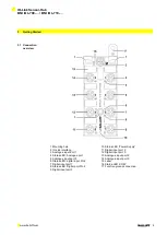
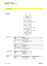
Страница 5: ...put Port 1 4 Status LED Analogue port 5 Analogue input port 3 6 Status LED digital input Pin 2 7 Digital input port 1 8 Status LED Digital port Pin 4 9 Digital input port 3 10 Status LED Power Supply 11 Digital input port 2 12 Digital input port 0 13 Analogue input port 2 14 Analogue input port 0 15 Label 16 Status LED COM 17 Function ground connection ...

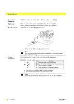
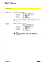
Страница 6: ...nal Connect Sensor Hub module to the ground terminal Note The FE connection from the housing to the machine must be low impedance and as short as possible 3 5 IO Link connection The IO Link connection is made using an M12 connector A coded male IO Link M12 A coded male Pin Function 1 Supply voltage 24 V max 1 6 A 2 3 GND reference potential 4 C Q IO Link data transmission channel Connection protec...

Страница 7: ...D 4 Standard Input 5 Note For the digital sensor inputs follow the input guideline per EN 61131 2 Type 2 3 7 Analogue Sensors Analogue input port M12 A coded female Pin Function 1 24 V 100 mA 2 BNI IOL 709 4 20 mA BNI IOL 710 n c 3 0 V GND 4 BNI IOL 710 0 10 V BNI IOL 709 n c 5 FE function ground Note Unused I O port sockets must be fitted with cover caps to ensure IP67 protection rating ...

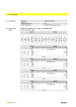
Страница 8: ...1 Port 2 Switch Point 1 Port 1 Switch Point 1 Port 0 Input Port 7 Pin 2 Input Port 6 Pin 2 Input Port 5 Pin 2 Input Port 4 Pin 2 Switch Point 2 Port 3 Switch Point 2 Port 2 Switch Point 2 Port 1 Switch Point 2 Port 0 Byte 2 Byte 3 7 6 5 4 3 2 1 0 7 6 5 4 3 2 1 0 Error 1 Error 2 Error 3 0 MSB Analogue value LSB Port 0 Byte 4 Byte 5 7 6 5 4 3 2 1 0 7 6 5 4 3 2 1 0 Error 1 Error 2 Error 3 0 MSB Analo...

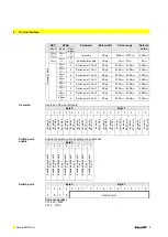
Страница 9: ...Measurement range overflow Measurement range undercut only CV 4 3 Process data outputs There are no outputs at BNI IOL 710 and BNI IOL 709 modules 4 4 Parameter data On request data DPP SPDU Parameter Data width Access Index Index Sub index Identification Data 07hex Vendor ID 2 Byte Read only 08hex 09hex Device ID 3 Byte 0Ahex 0Bhex 10hex 0 Vendor Name 8 Byte 11hex 0 Vendor text 16 Byte 12hex 0 Pr...

Страница 10: ...h point 2 Port 3 2 Byte 0000hex 03E8hex 0000hex Inversion Inversion of the input signals Byte 0 Byte 1 7 6 5 4 3 2 1 0 7 6 5 4 3 2 1 0 Inversion Port 7 Pin 4 Inversion Port 6 Pin 4 Inversion Port 5 Pin 4 Inversion Port 4 Pin 4 Inversion SP1 Port 3 Inversion SP1 Port 2 Inversion SP1 Port 1 Inversion SP1 Port 0 Inversion Port 7 Pin 2 Inversion Port 6 Pin 2 Inversion Port 5 Pin 2 Inversion Port 4 Pin...

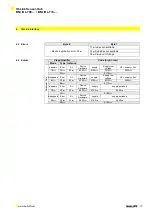
Страница 11: ...rs Error AL Device Hardware supply Supply low voltage U2 supply 24V C0hex 30hex 03hex 5000hex 0100hex 0010hex 0002hex F3hex 5112hex disappears Error AL Device Hardware supply Supply low voltage U2 supply 24V 80hex 30hex 03hex 5000hex 0100hex 0010hex 0002hex B3hex 5112hex appears Error AL Device Hardware supply supply periphery C0hex 30hex 03hex 5000hex 0100hex 0060hex F3hex 5160hex disappears Erro...

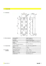
Страница 12: ...IP67 only when plugged in and threaded in Weight 90 g Dimensions L W H excluding connector 115 50 30 8 mm 5 3 Electrical data Operating voltage 18 30 2 V DC per EN 61131 2 Ripple 1 Current draw without load 40 mA 5 4 Operating conditions Operating temperature 5 C 55 C Storage temperature 25 C 70 C EMC EN 61000 4 2 3 4 5 6 Severity level 4A 3A 4B 2A 3A Vibration shock EN 60068 part 2 6 27 ...

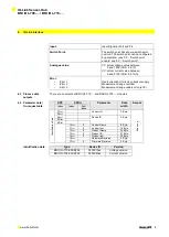
Страница 13: ...load Off Module unpowered LED 4 Power supply status Status Function Green Module power is OK Green slowly flashing Short circuit Green rapidly flashing Module power supply 18 V Off Module unpowered Digital Input LEDs LED 3 Input Pin 4 and LED 2 Input Pin 2 Status Function Yellow Input signal 1 Off Input signal 0 Analogue Input LEDs LED 1 Analogue input port Status Signal 709 4 20 mA Signal 710 0 1...

Страница 14: ...008 BNI IOL 7xx 000 K006 Balluff Network Interface IO Link interface Functions 710 8 digital inputs 0 15 A 4 analog inputs 0 10 V 709 8 digital inputs 0 15 A 4 analog inputs 4 20 mA Variant 000 Standardvariante Mechanical configuration K006 Plastic housing Connectors BUS and Power supply 1x M12x1 external thread Input ports 8x M12x1 internal thread ...

Страница 15: ...IO Link Sensor Hub BNI IOL 709 BNI IOL 710 www balluff com 14 Notes ...

Страница 16: ...www balluff com www balluff com Balluff GmbH Schurwaldstrasse 9 73765 Neuhausen a d F Germany Tel 49 7158 173 0 Fax 49 7158 5010 balluff balluff de Nr 910442 E Edition 1311 Subject to modification ...

Отзывы: