Balluff Network Interface / IO-Link
www.balluff.com
8
3
First steps
Mechanical
connection
The BNI IOL modules are attached using 2 M6 screws and 2 washers.
Electrical
connection
The BNI IOL-... modules do not require their own supply voltage. Supply voltage is provided
via the IO-Link interface and the higher-level IO-Link master module. You can however use
an additional AUX terminal for supplying the sensors and actuators connected to the module.
The connections are described in the previous section.
Function ground
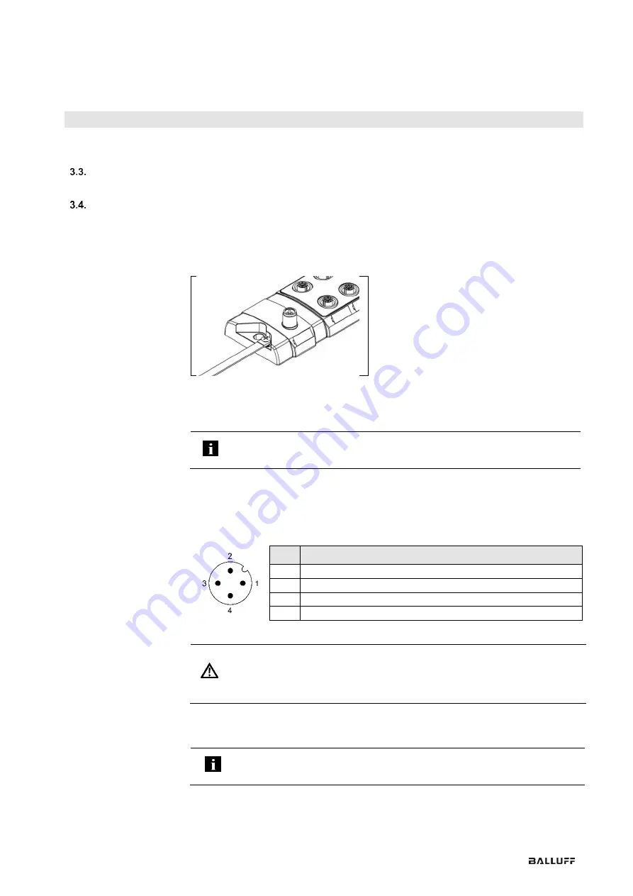
The modules are equipped with a ground connection (FE).
Fig. 3.2: FE connection
➢
Connect the sensor hub module to the ground connection.
Note
The FE-connection from the housing to the machine must have low impedance
and be as short as possible.
IO-Link
connection
The IO-Link connection is established via an M12 connector (A-coded, male).
This connection is used for supplying the module. For some devices this terminal is also
used for powering the sensors and/or actuators connected to the module.
IO-Link (M12, A-coded, male)
Pin
Requirements
1
Supply voltage for module (US1), +24 V, max. 4 A
2
Supply voltage for actuators (UA), +24 V, max. 4 A
3
GND, reference potential
4
C/Q, IO-Link data transmission channel
Attention!
Overcurrent.
Defective or missing fuses in the voltage supply for the sensor and
actuator will result in damage to them. Use a fuse or an intelligent power supply
(current monitoring designed for maximum 4 A) which turns off power when
overcurrent is present.
Connecting the
sensor hub
➢
Connect ground conductor to the function ground connection, if available.
➢
Connect the incoming IO-Link cable to the sensor hub.
Note
A standardized sensor cable is used to connect to the higher-level IO-Link master
module. Maximum length of 20 m.


