Quick Guide
English
BIS L-409-045-00x-07-S4
A
41
Страница 1: ...Quick Guide English BIS L 409 045 00x 07 S4 A 41...
Страница 2: ...www balluff com...
Страница 3: ...g of the warnings 7 Getting Started 8 3 1 Mechanical connection 8 3 2 Electrical connection 11 Basic knowledge 13 4 1 Function principle of Identification Systems 13 4 2 System topology 14 4 3 Read di...
Страница 4: ...ints Entry 1 Entry 2 Action instructions are indicated by a preceding triangle The result of an action is indicated by an arrow Action instruction 1 Action result Action instruction 2 Numbers Decimal...
Страница 5: ...age EMC Electromagnetic Compatibility LSB Least Significant Bit MSB Most Significant Bit PC Personal Computer SIO Standard IO SPDU Service Protocol Data Unit PLC Programmable Logic Controller TCP Tran...
Страница 6: ...owered only using approved power supplies see Technical data starting on page 16 Attention This is a Class A device This device may cause RF disturbances in residential areas in such a case the operat...
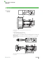
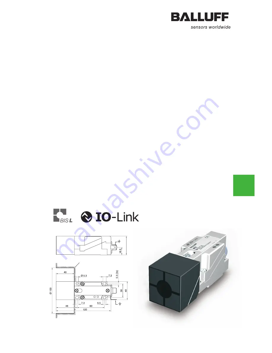
Страница 7: ...crews Note maximum tightening torque of 15 Ncm In addition to the processor with integrated read head the following processors with remote read head are available The processors with remote read head...
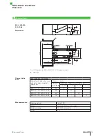
Страница 8: ...41 Fig 3 Processor BIS L 409 045 003 07 S4 dimensions in mm A Clear zone A A 41 Fig 4 Processor BIS L 409 045 004 07 S4 dimensions in mm A Clear zone Getting Started 3 BIS L 409 IO Link Device Process...
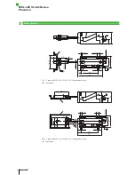
Страница 9: ...stance Y BIS L 409 001 1 m 1 m BIS L 409 002 0 5 m 0 3 m BIS L 409 003 0 5 m 0 3 m BIS L 409 004 0 5 m 0 3 m Note When installing two BIS L 409 on metal there is normally no mutual interference Unfavo...
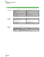
Страница 10: ...dicators on the processor Item LED Display Function 3 LED 1 green Supply voltage present 4 LED 2 yellow Tag Present IO Link port M12 A coded female PIN Function 1 24 V 2 NC 3 GND 4 C Q Connect data li...
Страница 11: ...is set using jumpers in the processor X4 IO Link mode jumper setting as shown in Fig 7 factory default setting Service mode to be used only by Balluff service The baud rate is set using two DIP switc...
Страница 12: ...a carrier signal which is picked up by the data carrier from within a certain distance As soon as the data carrier is powered up by the carrier signal a static read operation takes place The processo...
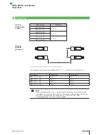
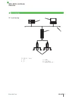
Страница 13: ...www balluff com 13 Fig 9 BIS L 409 topology 1 PLC 2 PC 3 ProfiBus 4 IO Link Master 5 Processors BIS L 409 4 2 System topology Basic knowledge 4 BIS L 409 IO Link Device Processor...
Страница 14: ...tion data carrier is powered by the read head using a carrier signal In order to ensure data integrity data transmission between the data carrier and processor can be monitored using a check procedure...
Страница 15: ...ta when used with data carriers installed in clear zone When v 0 static Distance mm read Offset from center axis at distance mm 0 20 0 35 0 45 0 15 BIS L 200 03 BIS L 100 05 25 15 BIS L 201 03 BIS L 1...
Страница 16: ...301 489 1 3 EN 61000 4 2 3 4 5 6 EN 300 330 1 Class A Level 3A 3A 4A 2A 3A Power class 5 Vibration shock EN 60068 Part 2 6 27 29 64 32 Two LEDs on the communications module indicate the status LED in...
Страница 17: ...ad Offset from center axis at distance mm 0 10 0 15 0 20 BIS L 200 03 BIS L 100 05 15 10 BIS L 201 03 BIS L 101 05 18 12 12 BIS L 203 03 BIS L 103 05 10 4 Housing material Plastic PBT Read head housin...
Страница 18: ...301 489 1 3 EN 61000 4 2 3 4 5 6 EN 300 330 1 Class A Level 3A 3A 4A 2A 3A Power class 5 Vibration shock EN 60068 Part 2 6 27 29 32 64 Two LEDs on the communications module indicate the status LED in...
Страница 19: ...zone When v 0 static Distance mm read Offset from center axis at distance mm 0 5 0 8 0 11 BIS L 203 03 BIS L 103 05 7 4 Housing material Plastic PBT Read head housing material CuZn nickel plated Wirin...
Страница 20: ...301 489 1 3 EN 61000 4 2 3 4 5 6 EN 300 330 1 Class A Level 3A 3A 4A 2A 3A Power class 5 Vibration shock EN 60068 Part 2 6 27 29 32 64 Two LEDs on the communications module indicate the status LED in...
Страница 21: ...ith data carriers installed in clear zone When v 0 static Distance mm read Offset from center axis at distance mm 0 10 0 15 0 20 BIS L 200 03 BIS L 100 05 15 10 BIS L 201 03 BIS L 101 05 18 12 12 BIS...
Страница 22: ...terface IO Link Ambient temperature range 0 C 70 C EMV EN 301 489 1 3 EN 61000 4 2 3 4 5 6 EN 300 330 1 Class A Level 3A 3A 4A 2A 3A Power class 5 Vibration shock EN 60068 Part 2 6 27 29 32 64 Two LED...
Страница 23: ...409 Plastic housing IO Link Software type 045 Software number IO Link Version 001 Coil 34 mm 002 Offset read head M18 0 5 m cable 003 Offset read head M12 0 5 m cable 004 Remote read head C 305 housi...
Страница 24: ...luff GmbH Schurwaldstrasse 9 73765 Neuhausen a d F Germany Phone 49 7158 173 0 Fax 49 7158 5010 balluff balluff de No 858280 00 000000 Edition 0805 Subject to modification www balluff com www balluff...