background image

© 2021 Baker Hughes Company. All rights reserved.

56  |  Baker Hughes

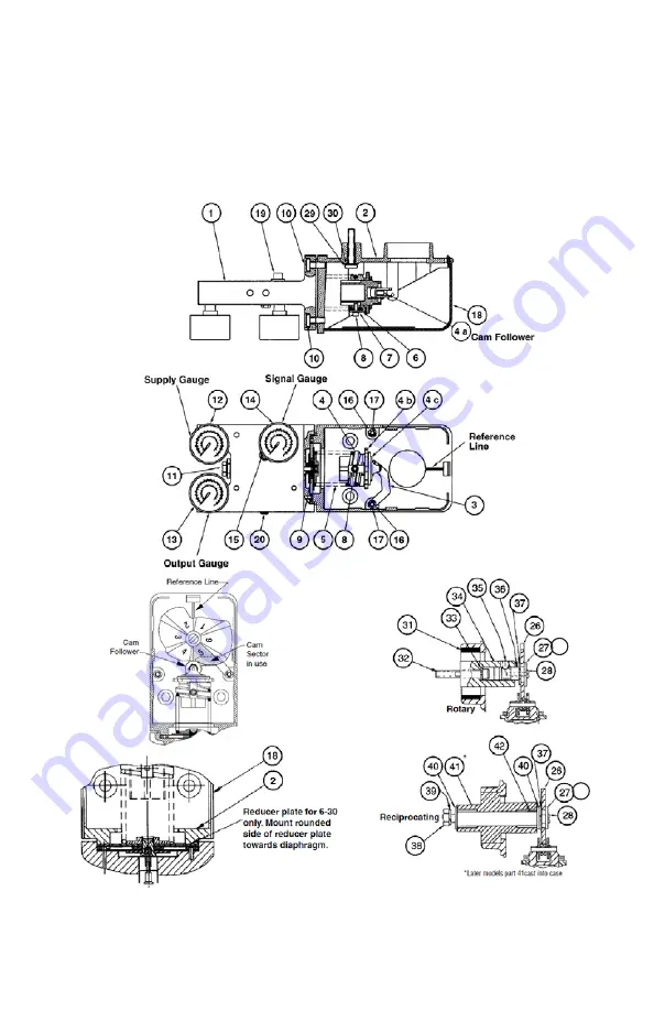
Parts Reference 4700P/4800P  

3-15 and 6-30 Range

Figure 18 - 4700P/4800P 3-15 and 6-30 Ranges

51

51

Содержание Masoneilan 4700P

Страница 1: ...Masoneilan 4700P 4700E 4800P 4800E Pneumatic and Electropneumatic Positioners Instruction Manual Rev F Baker Hughes Data Classification Public...

Страница 2: ...ENTS THEREFORE THESE INSTRUCTIONS SHOULD BE INTERPRETED AND APPLIED IN CONJUNCTION WITH THE SAFETY RULES AND REGULATIONS APPLICABLE AT THE SITE AND THE PARTICULAR REQUIREMENTS FOR OPERATION OF OTHER E...

Страница 3: ...n about post shipment calibration C 04 2015 Added Disclaimer paragraph and a new Figure 15 D 01 2020 Changed Valve Action references in High Performance Butterfly Valve cam and lever graphic in Calibr...

Страница 4: ...7 88 Actuators 17 Positioner Mounting and Orientation 19 Camflex II V Max MiniTork II and Butterfly 19 Pneumatic Installation 21 Electrical Installation of 4700E 4800E 24 Hazardous Area Installations...

Страница 5: ...lose Reverse Acting Positioner 4700P 4800P only 44 Damping Adjustment 45 Positioner Action Change 4700P 4800P Only 46 From Air to Open Direct to Air to Open Reverse 46 From Air to Open Reverse to Air...

Страница 6: ...Figure 10 Pneumatic Installation 23 Figure 11 Electrical Connections 24 Figure 12 FM Installation 30 Figure 13 CSA Installation 31 Figure 14 ATEX Installation 32 Figure 15 Split Range 33 Figure 16 Lob...

Страница 7: ...4700 4800 instructions contain WARNINGS CAUTIONS labels and Notes where necessary to alert you to safety related or other important information Total compliance with all WARNING and CAUTION notices i...

Страница 8: ...at heights per safe site work practices Use appropriate safety equipment and practices to prevent the dropping of tools or equipment during installation All surrounding pipe lines must be thoroughly f...

Страница 9: ...use a degradation of the performance of the system which can lead to personal injury or death Installation in poorly ventilated confined areas with any potential of gases other than oxygen being prese...

Страница 10: ...pneumatic positioner design is based on the force balance principle the signal pressure exerted on a diaphragm is opposed by a feedback spring In the balanced state when the pneumatic signal varies th...

Страница 11: ...instrument signal is applied directly to the positioner diaphragm and the regulated supply pressure flows through the pilot valve to or from the actuator The bypass valve module permits the positioner...

Страница 12: ...esponding to the low end of the signal range when removing or installing a cam At this point feedback spring compression is at lowest value and will facilitate cam removal or installation Prior to per...

Страница 13: ...over must be removed to access the zero and span adjustments and to mount the positioner on the valve To remove the cover Air to Open press the latch bar inward as shown in the figure below pull cover...

Страница 14: ...Hughes Figure 3 Rotary Figure 4 Reciprocating For 4700P 4800P model only positioner action can be reversed by simply engaging the proper lobe on the cam and reversing the follower arm numbers 1 and 2...

Страница 15: ...rnbuckle Screw 111 Positioner 30 Washer Shakeproof 102 Clevis 112 Male Connector 37 Ring Retaining 103 Back Lever 113 Cap Screw 38 Cap Screw 104 Clevis Pin 114 Lockwasher 39 Lockwasher 105 Retaining C...

Страница 16: ...2021 Baker Hughes Company All rights reserved 16 Baker Hughes Figure 5 87 88 Actuator...

Страница 17: ...ocation on the back lever Location is based on valve stroke required 5 Check Figure 6 for proper mounting location for positioner on bracket 6 Mount positioner on bracket using socket head screws 29 a...

Страница 18: ...Figure 6 87 88 Actuator Bracket Mounting Travel Settings 39 38 30 29 42 37 40 28 26 4A 41 40 135 27 51 103 2 5 2 0 1 5 1 0 0 8 Back Lever Top view of 4700P 4700E and 4800P 4800E Positioner Side view...

Страница 19: ...h gauges away from actuator on MiniTork II Figure 8 and HPBV 39004 Figure 9 The intermediate mounting plate 171 is held by two flat head screws 172 to the bracket NOTE The cam take off hole must be ce...

Страница 20: ...ights reserved 20 Baker Hughes Figure 7 Camflex II Figure 8 MiniTork II For detail of Positioner Mounting Parts see Figure 7 Figure 9 39000 Series High Performance Butterfly Valve For detail of Positi...

Страница 21: ...ctions of 4700P and 4800P and the output and supply connections of 4700P and 4700E are tapped 1 4 NPT The output and supply connections of 4800P and 4800E are tapped 3 8 NPT There is also an exhaust c...

Страница 22: ...nt malfunction The use of soft setting anaerobic hydraulic seal such as Loctite Hydraulic Seal 542 is recommended Follow manufacturer s instructions CAUTION Do not use an excessive amount as it will n...

Страница 23: ...Masoneilan 4700P E 4800P E Positioners Manual 23 2021 Baker Hughes Company All rights reserved Figure 10 Pneumatic Installation...

Страница 24: ...the output of the controller and verifying that at 100 controller output 20 mA is obtainable CAUTION Do not use a voltage source to drive the positioner as it may cause permanent damage CAUTION The p...

Страница 25: ...instructions You must make no changes or attempt any repairs of a certified instrument since this invalidates the certified design If a certified instrument should fail it must be returned to the manu...

Страница 26: ...I Division 2 Groups A B C and D S Class II and III Division 2 Groups F and G Temperature classification T4 40 C ambient T3B 70 C ambient T3A 85 C ambient Installation must be in accordance with the c...

Страница 27: ...ion 2 Groups A B C and D with a temperature code T6 75 C T5 85 C Install as per drawing 97 055 Figure 21 on page 62 Installation must be in accordance with the current edition of the Canadian National...

Страница 28: ...applicable country codes Figure 14 on page 32 and manufacturer s instructions Housing protection rating IP 66 Do not open when energized Do not open when an explosive gas atmosphere is present Use cab...

Страница 29: ...e Use denoted by X after the certificate number This enclosure is made from light metal which could cause ignition due to impact This shall be taken into consideration when the apparatus is installed...

Страница 30: ...2021 Baker Hughes Company All rights reserved 30 Baker Hughes Figure 12 FM Installation...

Страница 31: ...Masoneilan 4700P E 4800P E Positioners Manual 31 2021 Baker Hughes Company All rights reserved Figure 13 CSA Installation...

Страница 32: ...2021 Baker Hughes Company All rights reserved 32 Baker Hughes Figure 14 ATEX Installation...

Страница 33: ...4 20 mA control signal To accomplish this with the 4700E 4800E the two positioners are connected in series as shown in Figure 15 with the actual split ranging done by proper cam segment selection per...

Страница 34: ...own screw 32 with the lockwasher 33 is torqued to 125 inch lbs Mounting Cam The cam holder 36 and cam 26 are positioned on the cam coupling 34 so that the desired cam lobe s low signal line is properl...

Страница 35: ...to the left or right of the cam center Changing Lever S A Orientation See Field Mounting and Complete Calibration Rotary Actuators on page 54 and Field Mounting and Complete Calibration Reciprocating...

Страница 36: ...eld mounting maintenance etc it is necessary to follow all steps of the calibration instructions according to desired actuator action and positioner action For proper performance when the valve is ins...

Страница 37: ...or scale Span Adjustment See Figure 18 page 56 and Figure 19 page 58 If the valve does not fully stroke for a full signal span the feedback spring rate is too high Loosen screw 8 and turn spring 5 on...

Страница 38: ...e cam 26 on cam shaft with low signal line of desired lobe against cam follower Ensure the newly selected cam lobe is in the same relative position as the lobe noted in Step 2 4 Replace washer 27 lock...

Страница 39: ...ace washer 27 lockwasher 51 and screw 28 Check zero and span adjustment Refer to Zero Adjustment and Span Adjustment on page 37 Air to Close Reverse Acting Positioner See Figure 18 1 Shut off supply p...

Страница 40: ...cam lobe s low signal line on the cam follower 4A With the low signal line resting on the cam follower sight across the face of the cam to the raised reference line on the positioner case and align L...

Страница 41: ...19 page 58 1 Do not connect air supply or signal to the positioner Valve is now open 2 Note the valve position The travel indicator should be approximately aligned with the open end of the travel scal...

Страница 42: ...6 so that the selected cam lobe is facing forward and will rest on the cam follower Secure cam to cam holder with washer 27 lockwasher 51 and screw 28 Tighten screw 28 while holding the cam 26 7 With...

Страница 43: ...nut 4B and turnbuckle 106 until the low signal line of the cam is aligned with the positioner case raised reference line and the travel indicator shows closed position Retighten both locknuts 3 Apply...

Страница 44: ...locknut 107 Adjust zero by turning both the zero nut 4B and turnbuckle 106 until the low signal line of the cam is aligned with the positioner case raised reference line and the travel indicator shows...

Страница 45: ...Apply full scale value of instrument signal i e 15 psi and note position of stroke scale indicator If travel is not correct perform span adjustment Refer to Span Adjustment on page 37 7 Repeat zero a...

Страница 46: ...e pressure applied to actuator to zero If handwheel was used to place valve in open position back it off completely Valve is now closed Remove independent regulated air line from actuator 3 Proceed to...

Страница 47: ...e body 1 Note Turn the pilot subassembly while removing it to prevent damage to the O rings 2 Remove end plug and withdraw the spring plug and extension pin If necessary use a penetrating oil to free...

Страница 48: ...ver S A 3 and spring 5 4 On 4700E 4800E only remove 4 screws 21 to separate I P module from body CAUTION Do not damage or lose the three O rings on bottom of module 5 Remove cap screws 10 and separate...

Страница 49: ...ll the pilot assembly 11 and pressure gauges 5 Install the positioner on the actuator Reconnect air lines electrical leads if 4700E 4800E and coupling linkage if mounted on reciprocating valve 6 Assem...

Страница 50: ...ule 45 making sure they are seated in the bottom of the recess 4 Assemble to positioner using four 8 32 x 1 25 long screws 21 5 Reinstall vent plug instrument gauge and air connections Disassembly 1 T...

Страница 51: ...nnections must be correct for the positioner action i e direct or reverse Air tight connections Correct position of the bypass In case of malfunction check following in order given 1 Check zero adjust...

Страница 52: ...9 15 psig The following table shows for example the plug positions of two valves both air to close action open on air failure operating in split range with a 3 15 psig instrument signal Table 3 Split...

Страница 53: ...Masoneilan 4700P E 4800P E Positioners Manual 53 2021 Baker Hughes Company All rights reserved Cam Lobe Selection and Lever Arm Orientation Camflex II 87 88 Actuator...

Страница 54: ...2021 Baker Hughes Company All rights reserved 54 Baker Hughes Cam Lobe Selection and Lever Arm Orientation Cont MiniTork II counter clockwise motion V Max clockwise motion...

Страница 55: ...Masoneilan 4700P E 4800P E Positioners Manual 55 2021 Baker Hughes Company All rights reserved Cam Lobe Selection and Lever Arm Orientation Cont Butterfly Valves clockwise motion...

Страница 56: ...2021 Baker Hughes Company All rights reserved 56 Baker Hughes Parts Reference 4700P 4800P 3 15 and 6 30 Range Figure 18 4700P 4800P 3 15 and 6 30 Ranges 51 51...

Страница 57: ...r 30 Lockwasher 4B Zero Nut 31 Gasket 4C Zero Lock Nut 32 Socket Head Screw 5 Spring Feedback 33 Lockwasher 6 Clamp 34 Coupling 7 Lockwasher 35 Socket Head Set Screw 8 Socket Head Screw 36 Cam Holder...

Страница 58: ...2021 Baker Hughes Company All rights reserved 58 Baker Hughes Parts Reference 4700E 4800E Figure 19 4700E 4800E 51 51...

Страница 59: ...ut 32 Socket Head Screw 5 Spring Feedback 33 Lockwasher 6 Clamp 34 Coupling 7 Lockwasher 35 Socket Head Set Screw 8 Socket Head Screw 36 Cam Holder 9 3 15 Diaphragm S A 37 Truarc Ring 10 Screw 38 Cap...

Страница 60: ...y All rights reserved 60 Baker Hughes Parts Reference Ref No Description 19 Vent Plug 21 Screw 8 32 x 1 25 SEMS 45 Bypass S A 46 O ring 47 O ring 48 Valve Bypass 49 Ring Retaining 50 O ring Figure 20...

Страница 61: ...700 0 5 scf min 25 psig supply 4800 Temperature Effects Span Error Typical Temp Range C 40 to 20 20 to 60 60 to 85 Error 31 per C 06 per C 11 per C Supply Pressure Influence Less than 0 25 stroke chan...

Страница 62: ...2021 Baker Hughes Company All rights reserved 62 Baker Hughes Drawings Figure 21 Positioner and Cast Body Assembly...

Страница 63: ...Masoneilan 4700P E 4800P E Positioners Manual 63 2021 Baker Hughes Company All rights reserved NOTES...

Страница 64: ...2021 Baker Hughes Company All rights reserved 64 Baker Hughes NOTES...

Страница 65: ...Masoneilan 4700P E 4800P E Positioners Manual 65 2021 Baker Hughes Company All rights reserved NOTES...

Страница 66: ...es com Copyright 2021 Baker Hughes Company All rights reserved Baker Hughes provides this information on an as is basis for general information purposes Baker Hughes does not make any representation a...

Отзывы:

Похожие инструкции для Masoneilan 4700P