background image


OPERATOR’S MANUAL


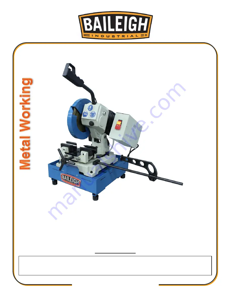
MANUAL COLD SAW 

MODEL: CS-225M-V2 


© 2020 Baileigh Industrial Holdings LLC 

REPRODUCTION  OF  THIS  MANUAL  IN  ANY  FORM  WITHOUT  WRITTEN  APPROVAL  OF  BAILEIGH  INDUSTRIAL 
HOLDINGS LLC IS PROHIBITED. Baileigh Industrial Holdings LLC, Inc. does not assume and hereby disclaims any 
liability for any damage or loss caused by an omission or er

ror in this Operator’s Manual, resulting from accident, 

negligence, or other occurrence. 

Rev. 03/2020 

Baileigh Industrial Holdings LLC 

P.O. Box 531 

Manitowoc, WI 54221-0531 

Phone: 920.684.4990 

Fax: 920.684.3944 

[email protected] 

Содержание CS-225M-V2

Страница 1: ...DINGS LLC IS PROHIBITED Baileigh Industrial Holdings LLC Inc does not assume and hereby disclaims any liability for any damage or loss caused by an omission or error in this Operator s Manual resulting from accident negligence or other occurrence Rev 03 2020 Baileigh Industrial Holdings LLC P O Box 531 Manitowoc WI 54221 0531 Phone 920 684 4990 Fax 920 684 3944 sales baileigh com ...

Страница 2: ...CAL 18 OPERATION 20 Miter Angle 20 Vise Operation 20 Loading the Piece Part 21 Setting Cut Length 21 Using the Stop Bar 21 Cutting Operation Cycle 22 MACHINE ADJUSTMENTS 23 Setting Saw Blade Head Stop 23 Blade Guard Adjustment 23 Changing the Saw Blade 24 MATERIAL SELECTION 24 CHOOSING A SAW BLADE 25 BLADE SELECTION CHART 26 LUBRICATION AND MAINTENANCE 27 Accessing and Cleaning the Coolant System ...

Страница 3: ...en notice to Seller of any suspected defect in the Goods prior to the expiration of the warranty period The original end user must also obtain a RGA from Seller prior to returning any Goods to Seller for warranty service under this paragraph Seller will not accept any responsibility for Goods returned without a RGA The original end user shall be responsible for all costs and expenses associated wi...

Страница 4: ...remedies provided under this Agreement or at law or equity Attorney s Fees In the event legal action is necessary to recover monies due from Buyer or to enforce any provision of this Agreement Buyer shall be liable to Seller for all costs and expenses associated therewith including Seller s actual attorney fees and costs Governing Law Venue This Agreement shall be construed and governed under the ...

Страница 5: ... Description of the functional parts of the machine Capacity charts Setup and start up instructions Machine operation Scheduled maintenance Parts lists GENERAL NOTES After receiving your equipment remove the protective container Do a complete visual inspection and if damage is noted photograph it for insurance claims and contact your carrier at once requesting inspection Also contact Baileigh Indu...

Страница 6: ...azardous situation which if not avoided will result in death or serious injury WARNING Indicates a hazardous situation which if not avoided could result in death or serious injury CAUTION Indicates a hazardous situation which if not avoided could result in minor or moderate injury NOTICE Indicates a situation which if not avoided could result in property damage IMPORTANT PLEASE READ THIS OPERATORS...

Страница 7: ...te dust mask Dust created while using machinery can cause cancer birth defects and long term respiratory damage Be aware of the dust hazards associated with all types of materials ROTATING BLADE HAZARD Moving saw blade may result in loss of fingers or limb DO NOT operate with guard removed Follow lockout tagout procedures before servicing Power Switch with Lock Out In the event of incorrect operat...

Страница 8: ...eigh does not recommend or endorse making any modifications or alterations to a Baileigh machine Modifications or alterations to a machine may pose a substantial risk of injury to the operator or others and may do substantial damage to the machine Any modifications or alterations to a Baileigh machine will invalidate the machine s warranty PLEASE ENJOY YOUR BAILEIGH MACHINE PLEASE ENJOY IT SAFELY ...

Страница 9: ... machine carefully check any part that appears damaged Check for alignment and binding of moving parts that may affect proper machine operation 15 Observe work area conditions DO NOT use machines or power tools in damp or wet locations Do not expose to rain Keep work area well lighted DO NOT use electrically powered tools in the presence of flammable gases or liquids 16 Blade adjustments and maint...

Страница 10: ... the machines specifications 30 Immediately release the start run trigger button if the saw blade should get stuck in a cut Press the red power off switch and remove the yellow lock key before raising the machine head Then open the vise and remove the work piece Check the blade teeth for damage If any of the teeth are broken or missing replace the saw blade 31 The operator should stand in front of...

Страница 11: ...mensions 28 x 20 x 25 711 x 508 x 635mm TECHNICAL SUPPORT Our technical support department can be reached at 920 684 4990 and asking for the support desk for purchased machines Tech Support handles questions on machine setup schematics warranty issues and individual parts needs other than die sets and blades For specific application needs or future machine purchases contact the Sales Department at...

Страница 12: ...mage painted surfaces Follow manufacturer s label instructions when using any type of cleaning product After cleaning wipe unpainted metal surfaces with a light coating of quality oil or grease for protection Important This waxy coating is NOT a lubricant and will cause the machine to stick and lose performance as the coating continues to dry WARNING SUFFOCATION HAZARD Immediately discard any plas...

Страница 13: ...port the weight of the saw body Do not lift alone Separate all parts from the packing material and check each item carefully Make certain all items are accounted for before discarding any packing material Head and Base Assembly Feed Handle Rubber Feet Material Stop ...

Страница 14: ...wer gently to the floor Level the machine so that all the supporting feet are taking the weight of the machine and no rocking is taking place INSTALLATION IMPORTANT Consider the following when looking for a suitable location to place the machine Overall weight of the machine Weight of material being processed Sizes of material to be processed through the machine Space needed for auxiliary stands w...

Страница 15: ...ce in place be sure to eliminate by using shims WORKING CLEARANCES Take into consideration the size of the material to be processed Make sure that you allow enough space for you to operate the machine freely POWER SUPPLY PLACEMENT The power supply should be located close enough to the machine so that the power cord is not in an area where it would cause a tripping hazard Be sure to observe all ele...

Страница 16: ...14 14 OVERALL DIMENSIONS Machine Dimensions when assembled 0 I REMOVE TO LOCK ...

Страница 17: ...ts the miter system vise system and head assembly Material Stop D The central part of the assembly housing the gear system and oil tank Stand E Support structure for the machine head assembly machine base and vise system The stand also houses the coolant tray Vise F A clamping system that provides the basic support and grip for the work material A hand wheel opens and closes the vise jaws Coolant ...

Страница 18: ...ght of the machine and the material to be cut Install the Rubber Feet 3 Carefully tip the machine on its side and install the four rubber feet I 4 Remove the oil fill transport plug from gear transfer case 5 Remove the packing material J 6 Use a wrench to unscrew an M20x40 hex screw from the oil fill hole K WARNING For your own safety DO NOT connect the machine to the power source until the machin...

Страница 19: ...to the vise 16 Loosen the clamping screw P to allow the bar stop to slide on the extension rod and allow clearance to turn the rod tight 17 Insert the threaded end of the bar stop extension rod Q into the mounting block on the right side of the machine base Turn cw until tight fully seated and tight 18 Attach the return springs 19 Raise the head assembly to the full up position and hold place 20 R...

Страница 20: ... indicated on the machine All line connections should make good contact Running on low voltage will damage the motor In the event of a malfunction or breakdown grounding provides a path of least resistance for electric current to reduce the risk of electric shock This machine is equipped with an electric cord having an equipment grounding conductor and a grounding plug The plug must be plugged int...

Страница 21: ...ts listed below LENGTH AMP RATING 25ft 50ft 100ft 1 12 16 16 14 13 16 14 12 12 17 20 12 12 10 21 30 10 10 No WIRE GAUGE An undersized cord decreases line voltage causing loss of power and overheating All cords should use a ground wire and plug pin Replace any damaged cords immediately Power cord connection 1 Turn the main switch on the control panel to the OFF position 2 Unwrap the power cord and ...

Страница 22: ... centering vise with both the front and back jaws move away from or toward the clamping center point 2 Use the hand wheel A to open and close the vise jaw B and secure the work material 3 Counter clockwise ccw to open jaws 4 Clockwise cw to close jaws CAUTION Always wear proper eye protection with side shields safety footwear and leather gloves to protect from burrs and sharp edges When handling l...

Страница 23: ...ength 1 Setting the cut length eliminates measuring duplicate pieces 2 Measure and mark the length of material to be cut off 3 Load the piece part 4 Line up the cut 5 Clamp the piece part 6 Loosen the hex nut A at the base of the stop riser 7 Slide the stop riser along the long rod so that the tip of stop riser B touches the end of the piece part 8 Tighten the hex nut at the base of the bar riser ...

Страница 24: ...the piece part forward for next cut 14 To turn off machine power press down on the power switch B 15 To stop machine in an emergency situation press the EMERGENCY STOP button B 16 Remove the yellow lock key A after use NOTICE Do not allow the saw to slam back up to the start position Doing so will cause damage to the pivot block and the weight of the motor will cause damage to the gear case adapto...

Страница 25: ...the stop bolt B in position and tighten the jam nut Blade Guard Adjustment To adjust the blade guard to cover the blade 1 The moveable guard should overlap the stationary guard just enough to completely cover the blade 2 If the blade is exposed at the overlap point A loosen the two socket head cap screws B and slide the link C up or down as needed to cover the blade 3 Hold the link C in position a...

Страница 26: ...om machine 7 Place washer and locating pin onto the replacement blade and follow above procedure in reverse 8 Check for proper blade rotation MATERIAL SELECTION When selecting materials keep these instructions in mind Material must be clean and dry without oil Material should have a smooth surface so it processes easily Dimensional properties of material must be consistent and not exceed the machi...

Страница 27: ...de tooth profile Choose a tooth pitch that is suitable for the workpiece Thin walled profiles including tubes and pipes require close toothing At least 3 6 teeth should be in contact with the material while cutting Large solid or transverse sections require widely spaced toothing to allow for greater volume of chips and better tooth penetration Soft materials such as plastics light alloys mild bro...

Страница 28: ...26 26 BLADE SELECTION CHART ...

Страница 29: ... LUBRICATION OIL TABLE 2 Below 82 F Select from the products listed below Brand Hydraulic Tank Oil Gear Oil Slideway Oil Mobil DTE XL 46 SHC 525 Mobilgear 630 SHC 220 Mobil Vactra Oil No 4 Shell Shell Tellus Oil 46 Shell Omala Oil 220 Shell Tonna Oil T220 Exxon Nuto H 46 Spartan EP 220 Febis K220 Brand Hydraulic Cylinder Oil Air Lube System Grease Fittings Mobil DTE 21 DTE 21 Mobil UX2 EPO Shell S...

Страница 30: ...an and grease the vise screw and sliding surfaces Clean the guard housing for the disk saw blade Sharpen the saw teeth Monthly Maintenance Check that all screws on the motor pump vise jaws and the guards are tight and secure Check that the saw guard is operating properly Oil the hinge pin for the head assembly Yearly Maintenance Change the oil in the gear case as follows 1 Lower the saw head to th...

Страница 31: ...ouring coolant through the chip strainer Oils for Lubricating Coolant Any 10 1 water to coolant solution will work however we recommend Baileigh B Cool 20 1 water to coolant biodegradable metal cutting fluid It has excellent cooling and heat transfer characteristics is non flammable and extends blade and machine life Each gallon of concentrate makes 21 gallons of coolant Storing Machine for Extend...

Страница 32: ...30 30 PARTS DIAGRAM ...

Страница 33: ...31 31 ...

Страница 34: ... 2 15 Pipe coupling 2 16 Coolant tube 3 17 Disc 1 18 Swivel Plate 1 19 Pivot Block 1 20 Shaft 1 21 Hex cap screw 2 22 Socket head cap screw 2 23 Socket head cap screw 2 24 Lead Screw 1 25 Guide rod 2 26 Retaining ring S13 2 27 Middle support 1 28 Socket head cap screw 2 29 Plate 2 30 Flat head screw 4 31 Cover 1 32 Support plate 1 33 Rear vise jaw 1 34 Front vise jaw 1 35 Jaw insert 2 36 Jaw inser...

Страница 35: ...crew 1 48 Socket head cap screw 1 49 Connector fitting 1 50 Fixed blade guard 1 51 Moveable blade guide 1 52 Socket head cap screw 1 53 Blade shaft flange 1 54 Blade shaft 1 55 Oil seal 1 56 Handle grip 1 57 Flat head screw 2 58 Limit switch 1 59 Cable 1 60 Handle 1 61 Hex nut 1 62 Head 1 63 Oil Plug 1 64 Bolt 5 65 Spring 2 66 Socket set screw 1 67 Worm 1 68 Oil spring glass 1 69 Ball Bearing 1 70...

Страница 36: ...er 1 80 Coolant Motor and Pump 1 82 Cable 1 83 Washer 2 84 Bolt 1 85 Cover 1 86 Screw 4 87 Spring Pin 2 88 Rubber sheet 1 89 Front cover plate 1 90 Cover 1 91 Stock Stop 1 92 Bolt 1 93 Bolt 2 94 Screw 2 95 Screw 2 96 Nut 2 97 Washer 5 98 Mounting Plate 1 99 Blade 1 100 Washer 6 101 Bot 2 102 Nut 4 103 Nut 4 104 Pin 1 ...

Страница 37: ...18 XX 1 SB1 Trigger Switch 15A 1 2HP 125 250VAC 0 6A 125VDC 1 KM1 FR Latching Relay Thermal Overload CN 6 600VAC 20A RHN 5M 9 12 5A 1 KA1 Relay Coolant Pump JZX 22F D 2Z 1 M1 Saw Motor 110V 60hz 1 HP 75kw 10 4A 1 M2 Coolant Motor 1 16hp 46 5w 24VCD 1 DCPS DC Power Supply 04 A0713A G E472249 XYJ 1 1 QF KM1 FR KA1 DCPS ...

Страница 38: ...36 36 ELECTRICAL SCHEMATIC M1 L1 N1 KM1 FR U1 W1 Main Motor KA1 2 FR 1 SB1 M2 Coolant KM1 PE QF AC110V AC110V DC POWER DC24V DC24V KA1 Pump L2 N2 4 3 W2 U2 DCPS ...

Страница 39: ... the dimensions of the part to be cut RIDGES ON THE CUTTING SURFACE Ineffective gripping of the part in the vise Too fast advance Disk teeth are worn Insufficient lubricating coolant Teeth do not unload shavings well Check the gripping of the part Decrease advance exerting less cutting pressure Sharpen the tool Check the level of the liquid in the tank Increase the flow of lubricating coolant chec...

Страница 40: ...ity type and construction characteristics Carefully clean the laying and contact surfaces BLADE STICKS IN THE CUT Too fast advance Low cutting speed Wrong tooth pitch Sticky accumulation of material on the disk Insufficient lubricating refrigerant Decrease advance exerting less cutting pressure Increase speed Choose a suitable disk Check the blend of lubricating coolant and choose a better quality...

Страница 41: ...icky accumulation of material on the disk Decrease advance exerting less cutting pressure Change disk speed and or diameter Choose a suitable disk Use a better quality disk Check the gripping of the part Accurately remove all the parts left in Make the cut elsewhere turning the part Check the level of the liquid in the tank Increase the flow of lubricating coolant checking that the hole and the li...

Страница 42: ...r quality disk Check the level of the liquid in the tank Increase the flow of lubricating coolant checking that the hole and the liquid outlet pipe are not blocked CHIPPED DISK Hardness shape or flaws in the material Wrong cutting speed Wrong tooth pitch Vibrations Disk incorrectly sharpened Low quality disk Incorrect emulsion of the lubricating coolant Reduce the cutting pressure and or the advan...

Страница 43: ...41 41 NOTES ...

Страница 44: ...ITOWOC WI 54220 PHONE 920 684 4990 FAX 920 684 3944 www baileigh com BAILEIGH INDUSTRIAL HOLDINGS LTD UNIT D SWIFT POINT SWIFT VALLEY INDUSTRIAL ESTATE RUGBY WEST MIDLANDS CV21 1QH UNITED KINGDOM PHONE 44 0 24 7661 9267 FAX 44 0 24 7661 9276 WWW BAILEIGH CO UK ...

Отзывы: