35
35
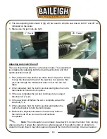
10. Place the blade around both the drive pulley and the idler
pulley. Make sure the back edge of the blade rests near the
flange (F) on both pulleys.
11. Turn the blade tension knob (D) clockwise (cw) to tension the
blade. DO NOT over tension. See the section titled “Adjusting
Blade Ten
sion”.
12. Close the blade cover, secure with the (2) screws, and slide
the drive pulley cover down.
13. Attach the wire wheel (C), the inner blade guard (B), and the
blade cover guard (A).
14. Lower the saw bow by releasing the cylinder lever.
15. Connect to the power source.
16. Run the saw and make sure the blade is tracking properly.
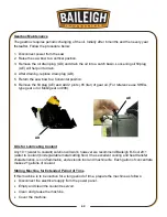
Adjusting Blade Guide Bearings
The blade guide bearings have been adjusted at the
factory. Over time, an adjustment will become necessary
due to uneven blade wear or skewed cuts. The side
bearings have an eccentric shaft to allow for side to side
adjustment.
1. Disconnect power to the saw.
2. Move the saw bow to the vertical position and lock in
place by turning off the hydraulic cylinder valve.
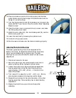
3. Loosen cap screw (X) in figure at right and adjust the
bearing assembly so that the back roller bearing is
ap
proximately .003”-.005” (.07mm - .13mm) from the
back of the blade.
4.
Turn nut(s) (Y) to adjust for a .001” - .002” (.02 - .05mm)
side clearance between the bearing and the blade.
5. Repeat the procedure for the side clearance of the other
bearing assembly. This assembly has no back bearing
adjustment.
6. Blade should still move up and down freely after
adjusting.
F
(.07 - .13mm)
(.02 - .05mm)
.003"-.005"
.001" - .002"
X
Y
Содержание BS-712MS
Страница 17: ...14 14 OVERALL DIMENSIONS...
Страница 18: ...15 15 GETTING TO KNOW YOUR MACHINE A B C D E F G H I K J L...
Страница 32: ...29 29...
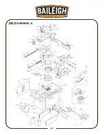
Страница 46: ...43 43 PARTS DIAGRAM A...
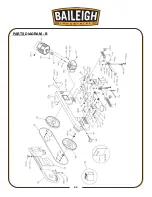
Страница 47: ...44 44 PARTS DIAGRAM B...
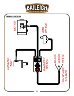
Страница 52: ...49 49 WIRING DIAGRAM MAGNETIC SWITCH COOLANT PUMP MOTOR 110V POWER SOURCE LIMIT SWITCH BLACK WHITE GREEN...
Страница 58: ...55 55 NOTES...
Страница 59: ...56 56 NOTES...

