Baileigh Industrial B8085 Скачать руководство пользователя страница 1

OPERATOR’S MANUAL 

ROTARY DRAW BENDER 

MODEL: RDB-250 (B8085) 

© 2015 Baileigh Industrial, Inc. 

Rev. 03/2015 

Содержание B8085

Страница 1: ...OPERATOR S MANUAL ROTARY DRAW BENDER MODEL RDB 250 B8085 2015 Baileigh Industrial Inc Rev 03 2015...

Страница 2: ...g 16 Programmer Display and Key Functions 16 Main Menu Choices 17 Edit a Program 18 Delete Program 19 Creating a Program 19 Dry Running 20 Running a Program 20 Manual Bend 21 Homing 23 OEM Screens and...

Страница 3: ...GRAM OPTIONAL EQUIPMENT 42 LUBRICATION AND MAINTENANCE 43 Gear Box Oil 43 Main Spindle Bearing 43 ELECTRICAL SCHEMATIC 44 Electrical Components 45 TROUBLESHOOTING 46 TABLES CHARTS DIAGRAMS 47 Diagram...

Страница 4: ...rect installation guidelines Description of the functional parts of the machine Capacity charts Set up and start up instructions Machine operation Scheduled maintenance Parts lists GENERAL NOTES After...

Страница 5: ...afety alert symbol DANGER identifies a hazard or unsafe practice that will result in severe Injury or Death Safety signs with signal word DANGER or WARNING are typically near specific hazards General...

Страница 6: ...ged exposure to loud noise can cause impairment or loss of hearing Wear suitable hearing protective devices such as ear muffs or earplugs to protect against objectionable or uncomfortable loud noises...

Страница 7: ...ial and the swing area in which the material will travel The material will swing with significant force This swing area will create pinch points and the force of the material movement may cause seriou...

Страница 8: ...tools Before operating the machine make sure any adjusting tools have been removed 4 Keep work area clean Cluttered areas invite injuries 5 Overloading machine By overloading the machine you may cause...

Страница 9: ...the presence of flammable gases or liquids 15 Keep children away Children must never be allowed in the work area DO NOT let them handle machines tools or extension cords 16 Store idle equipment When...

Страница 10: ...ly Round Tube Wall 2 125 50 8mm 3 175mm Mild Steel Solid Rod 1 25 31 75mm Mild Steel Square Tube Wall 2 125 50 8mm 3 175mm Maximum Speed to 180 9 Seconds Power Supply 240 VAC 15A 1ph 50Hz Sound level...

Страница 11: ...damage painted surfaces Follow manufacturer s label instructions when using any type of cleaning product After cleaning wipe unpainted metal surfaces with a light coating of quality oil or grease for...

Страница 12: ...that all the supporting feet are taking the weight of the machine and no rocking is taking place INSTALLATION IMPORTANT Consider the following when looking for a suitable location to place the machin...

Страница 13: ...by using shims WORKING CLEARANCES Take into consideration the size of the material to be processed Make sure that you allow enough space for you to operate the machine freely POWER SUPPLY PLACEMENT Th...

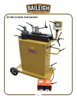
Страница 14: ...11 11 GETTING TO KNOW YOUR MACHINE A B C D E F G H I J K L M N...

Страница 15: ...mmable Bending Machine It has been carefully built of high quality materials and designed to give many years of efficient service The simplicity of design and minimum effort required to operate the ma...

Страница 16: ...should make good contact Running on low voltage will damage the motor In the event of a malfunction or breakdown grounding provides a path of least resistance for electric current to reduce the risk o...

Страница 17: ...d or if in doubt as to whether the tool is properly grounded Repair or replace damaged or worn cord immediately Extension Cord Safety Extension cord should be in good condition and meet the minimum wi...

Страница 18: ...m Operation is extremely simple to learn Simple foot pedal controls allow you to easily produce fast and accurate bends The following instructions will walk you through the basic functions Be sure to...

Страница 19: ...ay the RMD MAIN SCREEN see Fig 1 4 On the RMD MAIN SCREEN you can chose MANUAL MODE or RUN VIEW OR EDIT A PROGRAM Programmer Display and Key Functions 1 The touch screen control is very self explanato...

Страница 20: ...per program can be created using any alphanumeric characters b From the Program selector screen Fig 5 choose the program you wish to edit by touching the name of the program from the right side column...

Страница 21: ...eature when you want to edit an existing program a From the Program selector screen Fig 5 choose the program number to be edited Use the up and down arrows to move the screen up or down one line or on...

Страница 22: ...above steps to get to the edit screen Fig 6 Press and hold the F3 button below the CLEAR PROGRAM box to erase all of the bend data for the selected program Creating a Program 1 Choose RUN VIEW OR EDI...

Страница 23: ...From the Program selector screen Fig 5 press Run to run the program Dry Running Once you are familiar with the machine and programming unit it is important to dry run a few programs without any toolin...

Страница 24: ...only 1 bend is programmed bend 1 will be repeated until the program is exited and a different program is loaded Manual Bend Manual Operation has two control levels Manual Mode and Full Manual Mode Man...

Страница 25: ...trolling the stop point The speed is controlled with the arrow keys from speed 1 6 1 or 2 recommended The closer to bend capacity the slower the speed setting should be This operation should also be c...

Страница 26: ...ow the Motor Speed to the slowest position if having difficulties tapping the foot pedals to get the exact setting 2 To set the home position press the upper right corner of the screen Fig 1 to displa...

Страница 27: ...ctory Changing these parameters without consulting the factory will void the warranty This machine is capable of bending more than 180 degrees Contact your distributor about your application o It will...

Страница 28: ...vation of bi directional option should only be done at the factory Consult the factory for specific information OEM Screen Shots OP Screen Figure 1 OEM Screen Figure 11 OEM Screen Figure 12 OEM Screen...

Страница 29: ...26 26 OEM Screen Figure 14 OEM Screen Figure 15 OEM Screen Figure 16 OEM Screen Figure 17...

Страница 30: ...27 27 OEM Screen Figure 18 OEM Screen Figure 19 OEM Screen Figure 20 OEM Screen Figure 21...

Страница 31: ...28 28 OEM Screen Figure 22...

Страница 32: ...perfect 90 is obtained At that point document the actual machine degrees Full manual mode is the best place to do these tests Use the overbend amount and enter that value into the springback field MAT...

Страница 33: ...attempting to bend material This will ensure that bends are correct and provide a longer life to machine components When handling large heavy material make sure it is properly supported 1 To install t...

Страница 34: ...Or use the following formula Alternate arc length formula Example 6 0 clr x2 1212x3 14 37 699 37 699 360 0 1047 per degree 0 1047x 90 degrees 9 425 of material used for a 90 degree bend Once the arc l...

Страница 35: ...utton and choose program to run following the on screen instructions 2 Once the die set is properly installed and the desired program is loaded and performs as needed the correct size material can now...

Страница 36: ...position in the controller 7 Be sure there are no obstructions along the draw side of the material 8 Be sure to leave enough material past the plastic slide to produce the desired bend Left Right The...

Страница 37: ...s at the desired angle the material needs to be removed or advanced 2 Activate the reverse foot pedal As the die starts going backwards the counter die and its quick release will swing out of the way...

Страница 38: ...e D Tube outside diameter t Tube wall thickness a First bend arc angle H Height of offset b Second bend arc angle L Length of offset A First tangent R1 First radius B Straight between bends R2 Second...

Страница 39: ...required by the bending machine to form the bend Neutral Axis That portion of the pipe or tube that is neither in compression or tension O D Outside diameter in inches of the tube or pipe Out of Plane...

Страница 40: ...ly for polished aluminum Steel rollers would be used for non polished materials Some aluminum will crack as it is being bent 6061 T6 is very hard and may need to be annealed or ordered in the T 0 cond...

Страница 41: ...Note tighten clamps without material in the die The clamps are lift and turn so you can position them anywhere This allows the handles to clear the counter die mount during bending 4 Insert the materi...

Страница 42: ...material to be bent and repeat these steps Large Size Square When bending larger than 1 5 38 1mm thinner wall square tubing the counter die position seems to work better between 1 2 and 1 12 7 25 4mm...

Страница 43: ...casters It may be necessary to fasten or lock the machine in place to keep the machine from rotating instead of the index table The index table must be allowed to pivot and rotate with its wheels 2 W...

Страница 44: ...sert a piece of material through the hook arm of the die being used and insert through the chuck note If multiple parts are being produced the material should be marked so the linear chuck position ca...

Страница 45: ...42 42 INDEX TABLE LAYOUT DIAGRAM OPTIONAL EQUIPMENT...

Страница 46: ...ectancy of your machine Gear Box Oil The main Planetary Gear Box is lubed with 80W90 gear lube Check and replace the gear lube every 3 years or 200hrs of continuous use Main Spindle Bearing The only g...

Страница 47: ...44 44 ELECTRICAL SCHEMATIC Black J2 Connector Orange J1 Connector Horner XLE or XLT Hexle 102 or HE XT102 Programmer...

Страница 48: ...least 1 min before working on any circuit because the VFD capacitors may have energy stored Maintenance should be performed on a regular basis by qualified personnel Always follow proper safety precau...

Страница 49: ...ped top hook arm to prevent slipping Only the counter die should be lubed Poor bend results Worn counter die Worn die groove Wrong size material and or wall thickness Too tight of a clr Replace counte...

Страница 50: ...091 0 126 1 2 0 840 0 700 0 080 0 109 0 147 0 188 0 294 3 4 1 050 0 700 0 080 0 113 0 154 0 219 0 308 1 1 315 0 700 0 110 0 133 0 179 0 250 0 358 1 1 4 1 660 0 700 0 110 0 140 0 191 0 250 0 382 1 1 2...

Страница 51: ...0 6631 68 1 1866 9 0 1571 39 0 6806 69 1 2041 10 0 1745 40 0 6980 70 1 2215 11 0 1920 41 0 7155 71 1 2390 12 0 2094 42 0 7329 72 1 2564 13 0 2269 43 0 7504 73 1 2739 14 0 2443 44 0 7678 74 1 2913 15 0...

Страница 52: ...49 49 Diagram 1...

Страница 53: ...50 50 Diagram 2...

Страница 54: ...51 51 PARTS DIAGRAM Base Assembly Parts Diagram...

Страница 55: ...52 52 Control Box Parts Diagram...

Страница 56: ...53 53 Drive Assembly Parts Diagram...

Страница 57: ...54 54 Main Bending Assembly Parts Diagram...

Страница 58: ...SHER 4 21 STD 1 4 20 X 0 5 SHCS 4 22 ME M250 6A009 BOTTOM PLATE ME 250 1 24 M8 X 1 25 X 30 SHCS 2 25 M8 X 1 25 X 20 HEX FLANGE 2 26 ME M350 7A057 ELECTRICAL BOX PIVOT HUB 1 27 M10 X 1 5 X 8 SET SCREW...

Страница 59: ...CS 16 54 M250 6A015 V2 COUNTER BRACKET 1 55 M6 X 1 0 X 12 BUTTON HEAD 2 56 PP 0137 V2 FIAMA COUNTER 1 57 M300 6A066 HAND WHEEL 1 58 ME M300 7A034 HANDWHEEL MOUNTING HUB 1 59 M8 X 1 25 X 16 SHCS 6 60 M...

Страница 60: ...1071 3 4 DOWEL PIN 3 79 STD 3 8 LOCK WASHER 4 80 STD 3 8 16 X 16 HHCS 4 81 M200 COVER COVER M325 FRONT 1 82 M250 7A002 BEARING HUB 1 83 ME M250 7A008 M250 SPINDLE METRIC 1 84 STD M20 X 2 5 X 120 HEX...

Страница 61: ...58 58...

Страница 62: ...the off position before re connecting 14 Use correct amperage extension cords Undersized extension cords overheat and lose power Replace extension cords if they become damaged 15 Keep machine well ma...

Страница 63: ...of the formers 8 Understand the machines controls Make sure you understand the use and operation of all controls 9 Overloading Pipe Tube Bender Do not over load the machine by using material which exc...

Страница 64: ...and material Do not exceed maximum capacity Wear safety boots MEDIUM OR PUNCTURING MEDIUM ELECTRICAL C E CRUSHING Assessment H STRIKING B PLANT SAFETY PROGRAM No Hazard Identification Item Hazard Wear...

Отзывы: