background image

Page 5/24

Operating Instructions

BA 7020

Technical specifications subject to change without notice

Copyright according to ISO 16016

BA_7020_00_EN_MJ_4917

1.3  Personnel

Only qualified personnel may operate this positioner or work in its vicinity. Qualified personnel are individuals who 

are familiar with the set-up, installation, commissioning, operation and maintenance of the positioner and possess 

the required qualification for their activity. The required or prescribed qualifications include, amongst others:


Training / instruction and the authorization to switch electric circuits and devices / systems on and off in 

accordance with EN 60204 (DIN VDE 0100 / 0113) and the technical safety standards.


Training or instruction in accordance with the technical safety standards for the maintenance and use of 

appropriate safety equipment and personal protective equipment.


Explosion-protected versions of this device are to be operated only by personnel having undergone special 

training or instructions or being authorized to work on explosion-protected devices in hazardous areas.


First aid training.

Always work safely and never perform any work which might present a hazard to persons or damage the actuator 

or other property in any way.

1.4  Before starting work

Prior to starting any kind of work, check that the types specified here are identical with the specifications on the 

name plate of the positioner: 

Baelz 7020

1.5  During operation

Safe operation can only be ensured if transport, storage, assembly, operation and maintenance procedures are 

performed in compliance with the safety requirements, and are performed properly and competently.

1.5.1  Transport, installation and mounting

Observe the general installation and safety regulations for heating, ventilating, air conditioning and piping. Use 

tools properly and competently. Wear the required personal and other protective equipment.

1.5.2  Service and maintenance

Prior to maintenance or repair, make sure that the positioner is disconnected from the power supply by qualified 

personnel in accordance with DIN VDE standards. The positioner requires no maintenance. However, we 

recommend checking the proper function of the positioner at least once a year. 

For maintenance, the cover of the actuator has to be removed. Apart from this, no regular maintenance is 

necessary. 

1.6  Working environment

Please observe the information regarding working environment given in the specifications, chapter 

2.2. 

Содержание BA 7020

Страница 1: ...24 Operating Instructions BA 7020 Technical specifications subject to change without notice Copyright according to ISO 16016 BA_7020_00_EN_MJ_4917 Baelz 7020 Digital Positioner in a Motorized Linear A...

Страница 2: ...ND STORAGE 8 4 MONTAGE 9 4 1 Installation 9 4 2 Installation of controller 10 4 3 Connection to electrical supply 10 4 4 Electrical connection 10 5 QUICK START GUIDE 11 5 1 Switching on the Baelz 7020...

Страница 3: ...MISSIONING AND DISPOSAL 22 10 WIRING DIAGRAMS BAELZ 7020 23 10 1 Wiring diagrams for operation in safety mode 24 ANNEX A INSTRUCTIONS FOR OPERATION USING MODBUS A1 FUNCTIONAL DESCRIPTION A2 A2 OPERATI...

Страница 4: ...Any use other than the intended use mentioned above different tasks and operation with other power sources than those permitted is considered to be improper use In case of improper use the operator sh...

Страница 5: ...er perform any work which might present a hazard to persons or damage the actuator or other property in any way 1 4 Before starting work Prior to starting any kind of work check that the types specifi...

Страница 6: ...de Digitaler Stellungsregle baelz 7020 Ger Nr C 100001 FD 112 17 24V 50 60Hz Made in Germany W w Digitaler Stellungsregler baelz 7020 Ger Nr C 100003 FD 112 17 24V 50 60Hz Made in Germany W B lz Sohn...

Страница 7: ...x 5 mA Digital input 1 configurable eg summer winter switch Imax 5mA low 0 5VDC high 9 38VDC Re 5 5k Digital output 2 potential free auxiliary changeover switches configurable max 250 VAC 4A Analogue...

Страница 8: ...tration such as areas with heavy traffic industrial areas chemical plants sewage plants etc coastal areas and the open sea the actuators must have external parts made of non corrosive material and mus...

Страница 9: ...t installation ONLY operate actuator with valve fitted Danger of serious damage to actuator Operating the linear actuator without a valve can lead to the destruction of the actuator due to lack of a l...

Страница 10: ...provider Check that the supply voltage and frequency match those given on the name plate of the positioner and the name plate of the actuator motor The wire size should always correspond to the power...

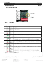
Страница 11: ...go 5 1 Switching on the Baelz 7020 Configure using DIP switches 1 4 and 7 10 before switching on For the first two seconds after switching on the unit cannot be operated and Modbus access is not avail...

Страница 12: ...r in standard mode In standard mode the positioner is set to heat In standard mode cooling can be selected by setting all three DIP switches 7 8 and 9 to position 1 Combination with split range or the...

Страница 13: ...ing diagram chapter 10 from 0 to 1 save 2EZ 1 2 DIP 6 Current position of the actuator is saved as second additional switching position 2EZ 1 See wiring diagram chapter 10 from 0 to 1 save 2EZ 2 98 DI...

Страница 14: ...arried out with DIP switches 7 8 and 9 set to 0 Cooling in standard mode is carried out with DIP switches 7 8 and 9 set to 1 Split range can be combined with heating in standard mode but not with cool...

Страница 15: ...oner operation on the red LED See also chapter 6 4 Initialisation run Function DIP 7 DIP 8 DIP 9 Linear 1 1 0 0 0 Split range split 50 offset 0 1 0 0 Split range split 50 offset 50 0 1 0 Split range s...

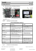
Страница 16: ...lisation run See FigFig 11 page 17 for meaning of LED signals An initialisation run can still be carried out but it will take approx 1x valve travel time longer During a successful initialisation run...

Страница 17: ...ble If the red LED is flickering the position of the potentiometer is at the edge of the optimal range and therefore OK 5 green and red flashing Error during initialisation Unit is not initialized The...

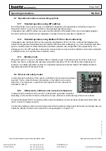
Страница 18: ...cated to an overriding external control system antifreeze excessive temperatures For external control the N S switch must be set to S safety mode 20 22 Digital input for a switch used to select betwee...

Страница 19: ...usted in standard mode but only take effect in Modbus mode 6 7 3 Modbus mode When DIP switch 11 is set to 1 the Baelz 7020 is in Modbus mode In Modbus mode the 7020 is at its most flexible and can be...

Страница 20: ...itialisation and those occuring during normal positioner operation Setting DIP switch 12 from 1 back to 0 permits the red LED to show any normal operational errors instead of initialisation errors whi...

Страница 21: ...ror codes during normal positioner operation In case of errors which cannot be rectified or are not covered in this documentation please contact Baelz see footer or contact your nearest Baelz customer...

Страница 22: ...on the positioner The name plate gives the correct technical specifications and power supply requirements of the unit Faulty or incorrect spare parts cause damage Attention Spare parts must comply wit...

Страница 23: ...ichnung Ursprung A S B _ 7 0 2 0 _ V 1 3 s k f nderung Gepr Bearb Datum TS 0 4 0 7 1 7 W B lz Anschlussbild baelz 7020 C o G m b H 2 3 26 38 Digital Positioner baelz 7020 GND A R 5kOhm PE N L Bl M Rd...

Страница 24: ...e Spindle extended valve closed excessive temp OT has priority Spindle extended valve closed antifreeze FP has priority Spindle extended valve open excessive temp OT has priority Spindle extended valv...

Страница 25: ...ng Instructions BA 7020 Technical specifications subject to change without notice Copyright according to ISO 16016 BA_7020_00_EN_MJ_4917 Baelz 7020 Digital Positioner Appendix A Instructions for Opera...

Страница 26: ...in both Modbus and standard mode However almost all configurations made using Modbus are not operative in standard mode These configurations will only be operative when DIP switch 11 is set to 1 A2 OP...

Страница 27: ...o main menu In the main menu send selection arrow to IMM Go to submenu highlighted by selection arrow Select parameters to modify selection arrow blinks Saves change Move selection arrow one place fur...

Страница 28: ...o create a backup copy of the 7020 configuration Enter the desired storage location under Dateiname file name This can be done either directly in the input bar or by using the Durchsuchen search butto...

Страница 29: ...Can be placed in front of M or V M Manual Manual operation Always set to A Automatic in standard mode V Value Numeric value manual specification Only active in extended Modbus operating mode A4 2 IVS...

Страница 30: ...alve running time Switching hysteresis of the three point controller Valve running time in seconds determined during initialization process Switching hysteresis in determined during initialization pro...

Страница 31: ...11 Coordinates UX1 to UY11 as part of an 11 point characteristic curve Set DIP switch 7 to 0 DIP 8 to 1 and DIP 9 to 1 to allow X and Y coordinates of an 11 point characteristic curve to be entered Ot...

Страница 32: ...figured limiting value AL1 is compared with AI1 first 2EZ in standard mode An alarm is issued when this limiting value is underrun AL1 is set either with DIP switch 5 see Chapter 6 3 or by entering 1...

Страница 33: ...e communication speed 0 19200 bits per second 1 9600 bits per second 2 4800 bits per second 3 2400 bits per second The connection to the PC is broken if the baud rate is changed using Modbus VT100 The...

Отзывы: