


Page 10/24
Operating Instructions
BA 7020
Technical specifications subject to change without notice
Copyright according to ISO 16016
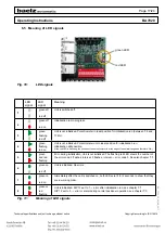
4.2 Installation of controller
Baelz recommends buying the positioner ready installed.
4.3 Connection to electrical supply
Risk of electric shock!
Use a safe electricity supply. Under no circumstances should dangerous voltage reach the equipment!
Safety fuses and cut-off switches must be available on site to protect from short circuiting and for activation of the
positioner. The required amperage can be derived from the current consumption of the electric actuator (see name
plate).
Only qualified and trained personell may carry out electrical installation.
● Take careful note of the basic instructions in this chapter before connection.
● After connection and before switching on the unit, take note of chapter
5.1 "Switching on the Baelz 7020".
● Ensure that the electrical supply is switched off when connecting to the mains! Safety measures to prevent
the supply being switched on unintentionally must be in place.
● For the installation of electrical cables and connections, observe the provisions for the installation of high-
voltage systems and the regulations set down by the local electricity provider.
● Check that the supply voltage and frequency match those given on the name plate of the positioner and
the name plate of the actuator motor.
● The wire size should always correspond to the power consumption of the linear actuator and the required
length of the wiring. The smallest permissible wire cross-sectional area for this linear actuator is 1 mm².
In case of failure: Dangerous voltage if operated without protective earth connection!
Risk of electric shock!.
→ Only operate with protective earth connection.
Trapped wires can cause short circuiting! Risk of electric shock and malfunction.
Danger
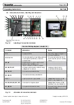
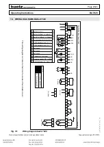
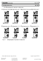
4.4 Electrical connection
Risk of electric shock!
Danger
Dangerous voltage! Risk of electric shock.
→ Disconnect from electricity supply before removing cover.
Connections should be carried out according to the wiring diagram on the inside of the cover, see chapter 10.
Replace dummy plugs with cable glands.
1. Strip end of cable insulation.
2. Strip ends of wires.
3. For flexible cable: Use wire end ferrules according to DIN 46228.
4. Connect cables according to the project-specific circuit diagram supplied.
Protection rating IP 42 is only guaranteed if suitable cable glands are used.
Compare the thrust of the actuator and the set distance of travel with the valve specifications. Overloading can
cause serious damage to the valve.
Beware of moving parts during installation and adjustment. Risk of injury and material damage.
Danger


