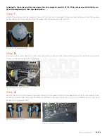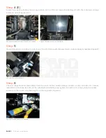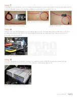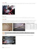
PAGE 7
|
Winch Installation
Step
17
Route wires with the spade connectors through an open spot in the dash and attach to the new switch at the
correct terminals before pressing the switch into the dash (Figures 22 & 23).
Step
18
Connect the green and black connectors at the opposite end of the switch cable to the top of the winch
controller (Figure 24).
Figure 6
of the winch installation manual details the wiring in a schematic for reference.
Step
19 (E)
Connect the red wire to the open connector on the winch wiring harness. No connector is needed (Figure 25).
Figure 22: Connected Switch
Figure 24: Switch to Controller Wiring
Figure 25: Electric UTV Red Wire
Figure 23: Installed Switch
Содержание 793-1086-00
Страница 12: ...1 B ad Boy Blvd Bat es ville A R BD 124 0 30...


