Winch Installation
|
PAGE 4
Step
7
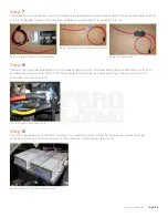
Assemble the circuit breaker kit with the positively indicated terminal connected to the short red cable. Enclose
the circuit breaker inside of the black box labeled “circuit breaker” (Figures 10, 11, & 12).
Step
8
Connect the newly assembled red circuit breaker cable and the included black cable to the battery with their
corresponding colors. Then attach the other ends of the cables the corresponding locations on the winch
controller module (Figure 13).
Step
9
The UTV is equipped with a DC/DC converter. To install the winch wiring harness, several wires must be
accessible which will include removal of the glove box compartment (Figure 14).
Figure 10: Battery Cable Kit w/ Circuit Breaker
Figure 13: Battery Cables to Controller
Figure 14: View of DC/DC Converter Under Hood
Figure 11: Positive Sticker to the Left Short Section
Figure 12: Cover Installed
Содержание 793-1086-00
Страница 12: ...1 B ad Boy Blvd Bat es ville A R BD 124 0 30...


