S
T
E
P
Part G
Part F
10
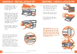
Step 10: Locate Part F. Insert ends of Part F onto swedge ends of both Parts G as shown in Box 19, by pushing down lock-
pins as in Box 20 until pins are fully engaged in lock holes as shown in Box 21.
Box 19
Box 20
Box 21
Step 11: Locate padded arms Parts J. Attach each Part J to Part E by inserting the 1 3/8” hex bolts through the holes in
Part J to the threaded holes located on the outside of parts E as shown in Box 22 & 23. Tighten each of the four bolts
securely using the hex wrench (Part X) as shown in Box 24.
Box 22
Box 23
Box 24
S
T
E
P
11
Step 12: Locate Part I. Attach Part I to back of Part E using the two ¾”
hex head bolts into the threaded holes on Part E as shown in photo.
Tighten securely using the hex wrench (Part X).
S
T
E
P
12


