


GDA-1600 16-Channel Controller
Instruction 5700-9001
20
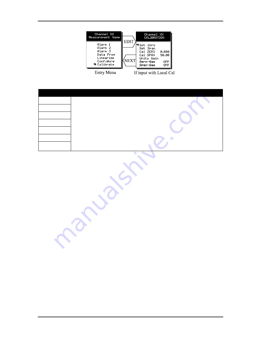
Figure 3.9
– Calibration Menus
Entries
Description
Set Zero
The CALIBRATION MENU allows for entering of the correct
Cal ZERO
&
Cal SPAN
set-
point values needed to calibrate the sensor. These are entered in the same
engineering units as input range.
Set Zero
&
Set Span
controls in this menu allow
pushbutton calibration by moving the pointer to each and pressing the
EDIT
key. A
live reading of the channel’s value allows calibration checks to see if an adjustment
is needed. Unintentional calibrations are reset by the
Unity Gain
menu item.
Unity
Gain
resets zero offset to 0 and span gain to 1. It is useful for returning the
calibration to a known starting place. Sensor aging may be monitored by recording
zero and span readings at
Unity Gain
when it is new, and again at later dates when
degradation may have occurred.
Set Span
Cal Zero
Cal SPAN
Unity Gain
Zero Gas
Span Gas
To check zero calibration, apply the ZERO calibration value to the sensor and observe
the live reading. If the zero reading differs from the zero setpoint, a calibration is
necessary. To calibrate zero, move the pointer to
Set Zero
and press
EDIT
. A warning
message explains that pressing
EDIT
again will change the zero calibration and any other
key will exit. The procedure for span calibration is identical. For example, if an LEL
combustible sensor is to be spanned with 50% LEL span gas, the span set-point must be
50%. If 45% LEL is to be used later, the span set-point must be changed to 45% in order
to match the span calibration gas. If the reading is only 40% LEL with the 50% gas
applied, a span calibration is needed. Move the pointer to the
Set Span
entry and press
EDIT
twice.
Unity Gain
may be used at anytime to cancel incorrect calibrations and
start again.
3.3
System Configuration Menus
Some items needing configuration are not specific to a channel but affect the entire
GDA 1600 system. These are located in the system entry menu shown on the left side of
Figure 3.10. System menus are accessed by pointing to the desired item and pressing
EDIT
.
Содержание GDA-1600
Страница 12: ...GDA 1600 16 Channel Controller Instruction 5700 9001 12 Figure 3 1 Channel Configuration Menus ...
Страница 21: ...Instruction 5700 9001 GDA 1600 16 Channel Controller 21 Figure 3 10 Configuration Menus ...
Страница 28: ...GDA 1600 16 Channel Controller Instruction 5700 9001 28 Figure 4 2 Main PCB ...
Страница 36: ...GDA 1600 16 Channel Controller Instruction 5700 9001 36 Figure 4 7 Analog Output Board ...
Страница 38: ...GDA 1600 16 Channel Controller Instruction 5700 9001 38 Figure 5 2 System Diagnostic Options ...
Страница 53: ...Instruction 5700 9001 GDA 1600 16 Channel Controller 53 ...


