background image

-29-

 2.

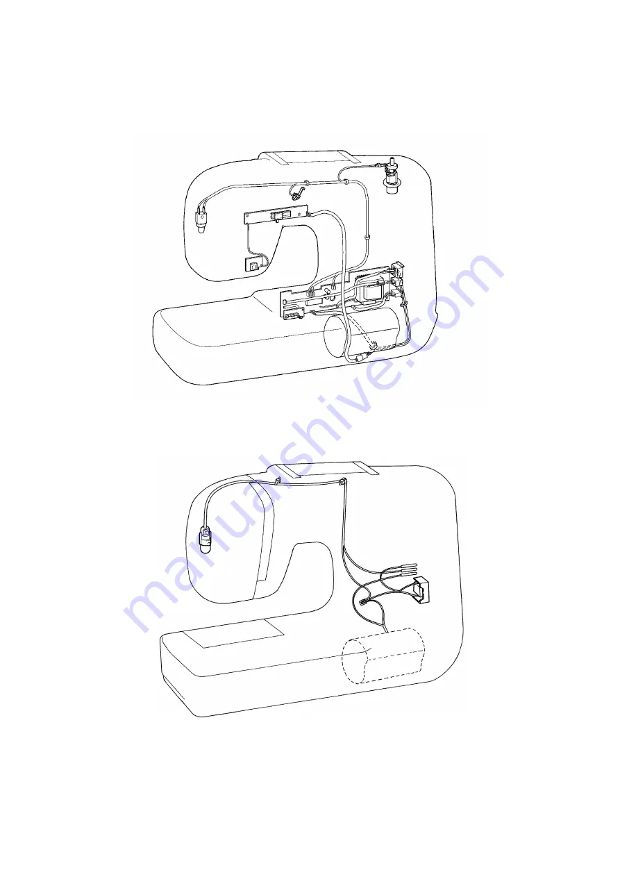
LEAD WIRES ARRANGEMENT

(BL6800)

(BL6300)

Содержание BL-6800

Страница 1: ...6 2001...

Страница 2: ...BL6800 1 Use the operation procedure given in this document 2 Always disconnect the power cord from the socket before starting to install or remove any parts 3 Always replace only with genuine Brother...

Страница 3: ...HART 2 2 POWER TRANSMISSION CHART 3 3 ELECTRONIC PARTS ARRANGEMENT CHART BL6800 only 6 4 CONTROL SYSTEM BLOCK DIAGRAM BL6800 only 7 5 MOTOR UNIT CONTROL BL6800 only 7 6 OTHER ELECTRONIC COMPONENT FUNC...

Страница 4: ...2 1 MECHANICAL CHART...

Страница 5: ...bar thread take up lever and zigzag movements Thread take up lever Thread take up crank Worm gear Timing pulley Needle bar crank rod Needle bar clamp Needle bar Needle bar block assembly Needle Patter...

Страница 6: ...Feed dog Feed carriage Vertical feed cam Horizontal feed plate Feed pattern cam Feed finger Feed regulator Horizontal feed shaft Horizontal feed cam pulley Forked connecting rod Horizontal feed arm L...

Страница 7: ...5 C Automatic 1 step BH mechanism BH change shaft BH change arm BH stopper BH cam BHF finger assembly BH Iever BH foot Feed control cam BH BHF finger assembly 2 A 2 B...

Страница 8: ...6 3 ELECTRONIC PARTS ARRANGEMENT CHART BL6800 only...

Страница 9: ...n the foot controller is used the speed does not become slow speed Speed adjustment volume a slide control used to set the sewing machine rotation rate Needle position NP sensor detects the drive timi...

Страница 10: ...8 II 1 DISASSEMBLING AND REASSEMBLING THE OUTER PARTS AND MAIN PARTS 9 2 LEAD WIRES ARRANGEMENT 29 3 MAIN PC BOARD ASSEMBLY REMOVEAL BL6800 Only 30...

Страница 11: ...bed attachment by sliding it to the left 3 Remove the six screws holding the front cover three on the rear two on the bottom one of the left then lift up the front cover from the bottom side open it f...

Страница 12: ...e rear of the sewing machine remove the 3 pin socket folder and then remove the three wiring harness bands for the lamp cord 6 Remove the screws holding the cord clamp 7 Remove the two screws holding...

Страница 13: ...for forked connecting rod remove the screws holding the Zigzag connecting rod adjustment nut and remove the Zigzag connecting rod 11 Remove the lock ring and the screw then remove reverse sewing leve...

Страница 14: ...tension spring from the needle bar block assembly 18 Remove the screws holding the needle bar supporter stud holder assembly then remove the needle bar supporter stud holder assembly 19 Remove the ne...

Страница 15: ...me remove the torsion spring 21 Loosen the presser bar clamp screw take out the presser bar and then remove the presser bar clamp and presser spring 22 Take the presser lifting shaft from the arm then...

Страница 16: ...5 Loosen the thread take up crank set screw then remove the needle bar crank and the needle bar crank rod Disassembly Point 24 Remove the left thread take up lever screw by holding the balance wheel b...

Страница 17: ...rotation prevention bracket then remove the inner rotary hook rotation prevention bracket 28 Remove the screw holding the inner rotary hook left retainer plate then remove the inner rotary hook left...

Страница 18: ...rizontal feed assembly center left then remove the horizontal feed shaft assembly 33 Remove the forked connecting rod 34 Loosen the rotary hook shaft set screw then remove the rotary hook assembly rot...

Страница 19: ...BH stopper assembly and spring 40 Remove the three screws securing the selection unit then remove the selection unit 41 Remove the M4 hex screw 42 Remove the screw securing the presser plate then rem...

Страница 20: ...regulator shaft and plastic washer A then secure with the fastening plate and screws Assembly Points 48 After installing the thread slack plate C rotate it and check that the force of the torsion spr...

Страница 21: ...the upper shaft through the timing belt and install with the two metal pressers and two screws Assembly Point 54 After installing the upper shaft rotate the balance wheel by hand and check that it rot...

Страница 22: ...n onto the rotary hook shaft in that order and secure with the screw Assembly Points 55 When installing the lower shaft check that the lower shaft rotates freely then align the timing of the upper and...

Страница 23: ...slide guide assembly with the screw 61 Pass the horizontal feed arm shaft through the horizontal feed arm and install the forked connecting rod 62 Install the lock ring on the horizontal feed shaft a...

Страница 24: ...9 67 Install the inner rotary hook rotation prevention bracket with the screw See Adjustment Procedure 10 68 Install the needle plate assembly with the screw and check the feed teeth left right posit...

Страница 25: ...eck that the needle bar crank rod rotates freely 69 Fasten with the contact surface flat surface of the needle bar crank rod screw at the screw A side When installing the screw A hold the balance whee...

Страница 26: ...ation plate install the BH lever installation plate with the two screws then install the BH change shaft and fasten with the screw Assembly Points 73 Pass the presser bar through the presser spring an...

Страница 27: ...the needle bar supporter stud holder assembly with the screw 77 Hang the needle bar block assembly tension spring on the arm and needle bar block assembly 78 Install the presser clamp on the presser...

Страница 28: ...the lock ring 85 Install the thread tension connecting rod assembly with the two screws Assembly Points 80 Install the feed bracket assembly screws in the order A then B After installing the feed bra...

Страница 29: ...hten the cord clamp and install with the screw 88 BL6800 Install the PC board assembly with the three screws then fasten the lamp cord with the three bundling bands BL6300 Install the 3 pin socket hol...

Страница 30: ...urface plate with the screw 92 Install the flat bed attachment Assembly Points 90 Pass the thread tension assembly and feed bracket assembly dial and Zigzag dial through the hole in the front cover an...

Страница 31: ...29 2 LEAD WIRES ARRANGEMENT BL6800 BL6300...

Страница 32: ...o pins gather the connector lead wires in a bundle and remove the connector without twisting the lead wires CN1 WB light Backstitch BK switch Bobbin winder BW switch CN1 WB light SS board CN2 BK CN3 B...

Страница 33: ...DIAL OUTER EDGE PLAY 46 16 PATTERN DISPLAY SELECTION POSITIONING 47 17 Z FINGER POSITIONING 48 18 FEED BRACKET INSTALLATION POSITION 49 19 SUPER PATTERN TRIPLE SEWING 50 20 FEED ADJUSTMENT 51 21 BH LE...

Страница 34: ...stment Procedure 20 BHF back feed forward reverse See Adjustment Procedure 22 BH needle descent adjustment See Adjustment Procedure 21 BHF bar tack feed See Adjustment Procedure 23 Z finger position i...

Страница 35: ...from the upper shaft horizontal feed cam pulley section and the tension pulley and the lower shaft timing pulley 2 Align the alignment mark for the upper shaft horizontal feed cam pulley and the align...

Страница 36: ...ard and back 6 Secure the tension pulley assembly with the screw Adjustment Points Driving belt Unplug the power cord before adjusting the driving belt This is done to avoid the possibility of electri...

Страница 37: ...moved 5 Tighten the two screws for the Zigzag dial assembly 6 Turn the balance wheel through position where the Z finger mounts the peak of the pattern cam 7 Loosen the screw holding the eccentric nu...

Страница 38: ...asten the needle bar at a position where the distance from the needle plate top surface to the needle tip 14 is 5 6 mm 5 Turn the worm gear or pattern cam to put the Z finger and pattern cam in the st...

Страница 39: ...urn the balance wheel and drill a small hole in the paper with the tip of the needle for left needle descent 4 Turn the selection dial and left straight line sewing 5 Loosen the screw securing the ecc...

Страница 40: ...ht needle descent positions the needle does not touch the rotary hook assembly point Adjustment Points If there is a difference in the clearances between the rotary hook assembly point and the routing...

Страница 41: ...up and down and align within the range 1 0 1 4 mm 5 Tighten the screw securing the needle bar holder Adjustment Points 5 When adjusting the needle bar height the needle bar is turned easily and this...

Страница 42: ...ENT 1 Loosen the screw securing the inner rotary hook retainer plate L 2 Adjust the vertical position of the inner rotary hook retainer plate L and adjust so that the clearance between the inner rotar...

Страница 43: ...prevention bracket 2 Adjust the forward back position of the inner rotary hook rotation prevention bracket so that the hanging difference for the inner rotary hook rotation prevention bracket spring a...

Страница 44: ...rward for the maximum feed distance ADJUSTMENT 1 Turn the feed dial to maximum 2 Turn the selection dial to straight line sewing 3 Loosen the screw securing the horizontal feed plate 4 Align the feed...

Страница 45: ...t the feed dog height is 0 9 1 1 mm at the center of the feed dog 4 Tighten the screw securing the vertical feed finger Adjustment Points If the feed dog height is not correctly adjusted the following...

Страница 46: ...nd down and adjust so that the distance between the top surface of the needle plate and the bottom surface of the presser foot is 6 0 6 5 mm 4 Tighten the screw securing the presser bar clamp Adjustme...

Страница 47: ...tension nut 3 Pull the thread slowly with the tension gauge in the direction shown in the figure and adjust by turning the thread tension adjustment screw so that the reading on the tension gauge is 0...

Страница 48: ...T 1 Loosen the screw securing the presser plate 2 Rotate the selection dial bearing to adjust the play 3 Tighten the screw securing the presser plate Adjustment Points 2 Turning the selection dial bea...

Страница 49: ...dial is turned the appropriate pattern display comes to the center of the display window on the front cover Adjustment Point This adjustment is not normally required After installing the front cover i...

Страница 50: ...tive to the cam 2 Turn the selection dial to zigzag sewing and loosen the two screws securing the indication gear 3 Move the selection cam left and right and align the Z finger and the pattern cam cen...

Страница 51: ...in the order C D Adjustment Points 2 If the feed dial gear alignment mark and idle gear alignment mark do not match remove the idle gear lock rating move the gear meshing to lineup the alignment marks...

Страница 52: ...e forward and reverse stitches 4 Tighten the feed adjuster nut Adjustment Points 3 Turning the adjustment screw to the right increases the reverse stitch length turning it to the left increases the fo...

Страница 53: ...tance to 1 8 2 2 mm 4 Tighten the adjustment screw nut Adjustment Points 3 Adjust by moving the feed dial gear position left and right so that when normal paper is laid under the presser foot and the...

Страница 54: ...er the tip of the needle to the paper with left needle descent 4 Turn the selection dial to button hole 5 Turn the balance wheel and lower the tip of the needle to the paper with left needle descent 6...

Страница 55: ...the selection dial interferes slightly with the box driver remove the selection dial screw and the selection dial beforehand 4 Turning the adjustment screw to the left makes the left reverse stitches...

Страница 56: ...interferes slightly with the box driver remove the selection dial screw and the selection dial beforehand 3 To forward the bar tack turn the adjustment screw to the left To reverse the bar tack turn t...

Страница 57: ...ark 2 on the BH lever 3 Tighten the BH change arm set screw 4 Loosen the screw securing the eccentric nut 5 Turn the eccentric nut and align with 0 5 1 1 N 50 110 gf on the BH lever return side The ad...

Страница 58: ...bobbin groove and the thread winding shaft spring position should be aligned 2 If the thread winding thread guide screw is loosened too much the nut will fall into the sewing machine so be careful no...

Страница 59: ...screw to match the lengths for forward stitches and reverse stitches Adjustment Point 4 Turning the adjustment screw to the right increases the length for reverse stitches 27 INNER ROTARY HOOK TENSION...

Страница 60: ...tter 5 Check the needle stop position the same as in Step 1 Adjustment Points 3 Turning the rotation shutter in the A direction raises the needle stop position turning the rotation shutter in the B di...

Страница 61: ...t for a feed of 3 the switch does not come ON in the reverse sewing lever play range range in which the feed adjuster is not pressed 3 Tighten the backstitch switch screw 30 BOBBIN WINDER SWITCH ADJUS...

Страница 62: ...eedle threader accepts only the circled needle and thread combinations 2 Combinations marked with can be used but are not recommended since they might lead to the break each of needle threader perform...

Страница 63: ...ecuring the needle threader base 3 Move the needle threader base left and right and adjust so that the hook comes to the center of the needle hole then tighten the two screws securing the needle threa...

Страница 64: ...EDLE THREADER 1 Removes the two screws securing the hook 2 Install the new hook then tighten the two screws securing the hook 3 If the threader hook does not enter the needle hole correctly adjust the...

Страница 65: ...ad breaks 64 8 Needle breaks 65 9 Noise 65 10 Forward and reverse feedings differ 65 11 Improper length of buttonhole legs 65 12 Improper buttonhole size against button size 65 13 Unbalanced patterns...

Страница 66: ...Thread correctly 5 Upper thread breaks during sewing 1 Bent or blunt needle 2 Improper setting of needle 3 Thread tension is too tight 4 Thread is tangled 5 Inferior needle eye 6 Inferior needle slot...

Страница 67: ...feedings differ 1 Improper adjustment of reverse sewing lever 1 Refer to P 57 11 Improper length of buttonhole legs 1 Improper adjustment 1 Adjust screw Refer to P 54 12 Improper buttonhole size agai...

Страница 68: ...and pattern indicator plate are not aligned correctly 1 Adjust the release volume Refer to P 37 2 Adjust the pattern indicator Refer to P 47 17 Light is off 1 Inferior light bulb 1 Replace the light...

Страница 69: ...sted 72 6 Needle does not stop in the up position 72 7 The sewing machine does not turn when the reverse sewing switch is pressed or if the switch is pressed during operation it does not go into low s...

Страница 70: ...nector SS board CN1 WB light CN2 BK CN3 BW CN4 FC Sensor board Speed VR board Motor Main PC board CN1 WB light Inlet Power supply switch Controller FC jack Motor Backstitch BK switch Bobbin winder BW...

Страница 71: ...PC board BL6800 only CN8 Inlet Power supply input CN7 Power supply switch CN6 SS VR board Sensor board LJ1 FG Line CN4 Foot controller jack CN3 Bobbin winder switch CN2 Reverse sewing switch CN1 Lamp...

Страница 72: ...70 SS VR board BL6800 only 1 pin Start Stop switch Speed volume...

Страница 73: ...VR PC board assembly connector On 1 max Off Infinite 4 Is the reverse sewing switch normal Resistance between 1 2 on connector CN3 yellow On 1 max Off Infinite 5 Is the resistance 1 max between 2 3 o...

Страница 74: ...sensor PC board assembly and main PC board assembly installation normal Are they floating loose or tilted 3 Is the bobbin winder switch normal Resistance between 1 2 on connector CN3 red On 1 max Off...

Страница 75: ...troller plug vary between 0 and 10 k 2 Is the resistance normal between 2 3 of CN4 on the pin jack assembly PC board When plug inserted Infinite When plug removed 1 max 3 Others 1 Replace the foot con...

Страница 76: ...BL 6800 BL 6300 H1060208...

Отзывы: