


Parts of the System
● Filter system with filter cartridges
● Installation hardware (mounting screws, saddle valve, flow restrictor, fittings)
● 1/4-inch (6.35mm) tubing
● Lead-free faucet
Materials and Tools Needed
Note:
Gather the required tools before starting installation. Read and follow the instructions
provided with any tools listed here.
•
Safety glasses
•
Hand or electric drill (cordless recommended)
•
File or sandpaper
•
Phillips Head screwdriver
•
2 adjustable wrenches
•
Tube cutters or utility knife
**If sink does not have hole for separate faucet:
•
Center punch
•
3/4-inch (19mm) drill bit
•
Masking tape
IMPORTANT:
To avoid damaging the sink, consult a qualified plumber or installer for drilling procedures in
porcelain, granite, or stainless steel.
Installation Instructions
NOTE:
A squeaking sound when tightening a compression nut is normal.
NOTE:
If fittings are removed, Teflon® tape must be used for pipe threaded connections.
NOTE:
Be sure to wear safety glasses when using a drill.
•
System is designed for standard under-sink installation on 3/8”-inch (10mm) cold water line.
•
Numbered diagrams correspond with numbered steps.
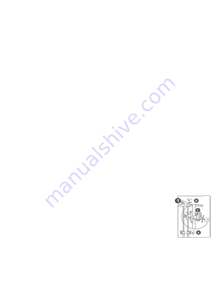
Step 1 – Installing the Saddle Valve
Use of a cordless drill is recommended. To protect yourself from serious injury or fatal
shock when using an electric drill, be sure the drill and the outlet it is plugged into are
properly grounded. When using a drill, follow the manufacturer’s guidelines and procedures.
NOTE: Saddle valve must be installed on a 2-inch (51mm) long, straight-walled section of
3/8-inch to 7/8-inch (10-22mm) steel, brass, copper, or PVC pipe
a)
Turn off cold water supply and turn on nearest faucet before starting installation.
Place a tray or towels under the cold water line to catch excess water.
b)
Drill a 1/8-inch (3mm) hole in the cold water line. Remove any burrs with sandpaper
or file.
c)
Turn handle on the saddle valve to expose lance no more than 3/16-inch (5mm)
above black rubber gasket.
d)
Place valve body over hole in cold water line so lance fits into hole.
e)
Attach back plate of clamp and tighten bolts evenly and firmly so brackets are parallel.
f)
Turn valve handle clockwise to closed position and leave closed until installation is compete.
NOTE:
All nuts must be retightened when the system reaches projected operating temperature.