


1-5
Chapter 1. ETHERCAT COMMUNICATION
■
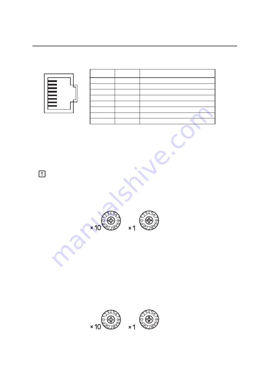
Communication connector pins
The network ports of this device are used as follows.
Pin No.
Signal
Description
1
TX +
Transmitted data (+)
2
TX -
Transmitted data (-)
3
RX +
Received data (+)
4
-
75 Ω terminating resistor connection
5
-
75 Ω terminating resistor connection
6
RX -
Received data (-)
7
-
75 Ω terminating resistor connection
8
-
75 Ω terminating resistor connection
Use STP (shielded twisted pair) cables, Cat. 5e or higher. Either a straight cable or a
crossover cable can be used.
Connect the network cable from the master device to the IN port (RJ-45 connector)
of this device. Additionally, if this device has a slave on the downstream side, con-
nect the OUT port (RJ-45 connector) of this K1G to the IN port of the slave device
with a network cable.
Handling Precautions
•
Do not use the EtherCAT communication network for other Ethernet
communications.
■
ECAT ID setting switches
Use these switches to specify an ECAT ID as a two-digit hexadecimal value. The
switches with ×10 and ×1 labels correspond to the 2nd and 1st digit of the hexa-
decimal number respectively. If no ECAT ID is used, set these rotary switches to the
“00” position.
The settings for the ECAT ID are read only when the power is turned on. If the
settings are changed during operation, the ECAT ID will not reflect the new set-
tings. A new ID set by the switches will be valid only after the power of the device is
turned off and back on.
Setting range: 00 to FF (decimal 0 to 255)
Factory default: 00
Example:
The above figure shows the following ECAT ID.
0x10 × 0x0C + 0x0C = 0xCC (204 in decimal)
⑧
Connector (jack) on this device
①
Содержание K1G Series
Страница 6: ......
Страница 24: ...Memo...
Страница 26: ...Memo...
Страница 29: ...Revision History CP SP 1419E Printed Edn Revised pages Description June 2017 1...
Страница 32: ...1st edition June 2017 V...