Axnes AS
Document number
Revision
Date
AX-PNG-UMAN-1219
Issue C
2018-Jun-05
Page 1-1
Confidential document and information
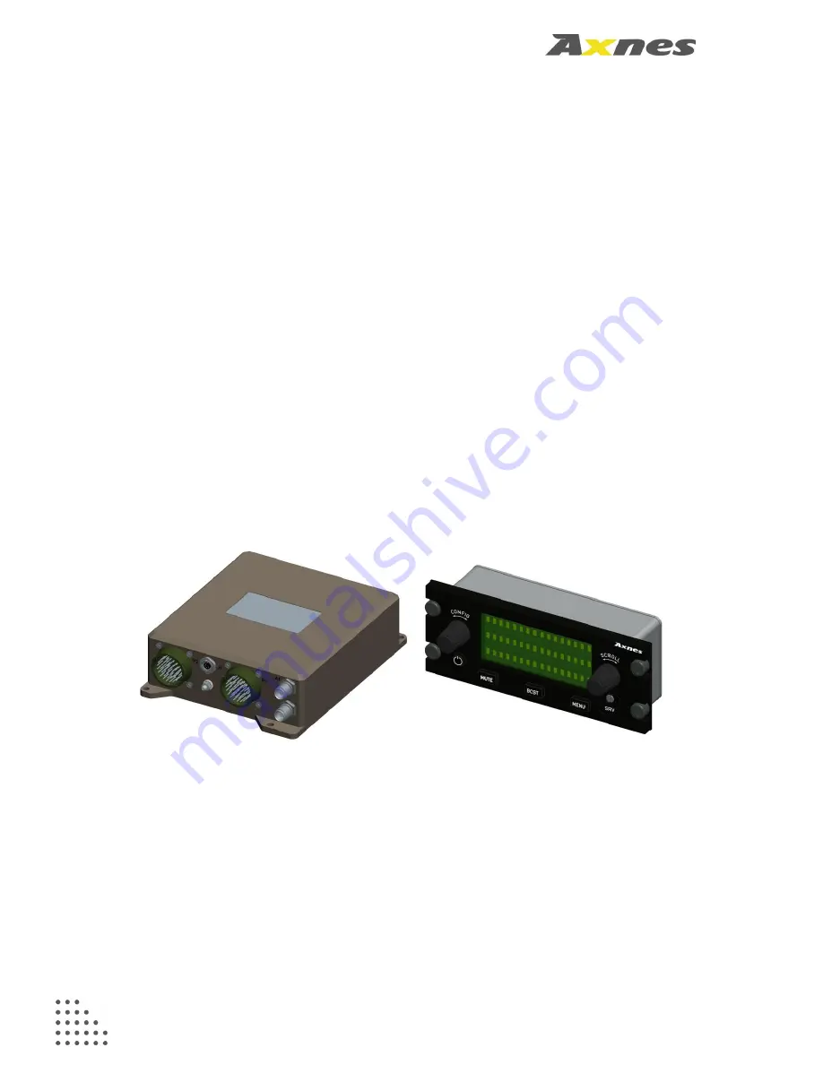
PNG BST50 Base Station Release 2
with AXS-SW-0311 software
and
PNG CP50 Control Panel
Operation Manual
Document number:
AX-PNG-UMAN-1219
Revision:
Issue C
Date:
2018-Jun-05


